Backup method for storage system

a storage system and data backup technology, applied in the field of storage systems, can solve problems such as user errors, data utilized by applications in host computers, and data loss

Active Publication Date: 2012-05-22
HITACHI LTD
View PDF12 Cites 24 Cited by
  • Summary
  • Abstract
  • Description
  • Claims
  • Application Information

AI Technical Summary

Problems solved by technology

Data utilized by an application (will be called “AP” hereinafter) in a host computer may be lost in accordance with “a failure of the storage apparatus”, “the destruction of data by a computer virus”, and “user error”.
Furthermore, AP “quiescence” also requires that work processing be suspended for a fixed period of time, lowering work efficiency.
However, in a case where a backup is performed in VM units by staticizing the AP, the problem has been that only the VM backup time is capable of being managed and the AP recovery time is indiscernible even by referencing the backup catalog.
Accordingly, for the user, this gave rise to the problem that processing that depended on the recovery time, such as AP recovery time-based recovery management, could not be carried out.
For this reason, the problem has been that the user is not able to carry out processing that depends on the recovery time, such as AP recovery time-based recovery management.

Method used


Image

  • Backup method for storage system
  • Backup method for storage system
  • Backup method for storage system

Examples


first embodiment

[0042]First, a first embodiment of the present invention will be explained using FIG. 1.

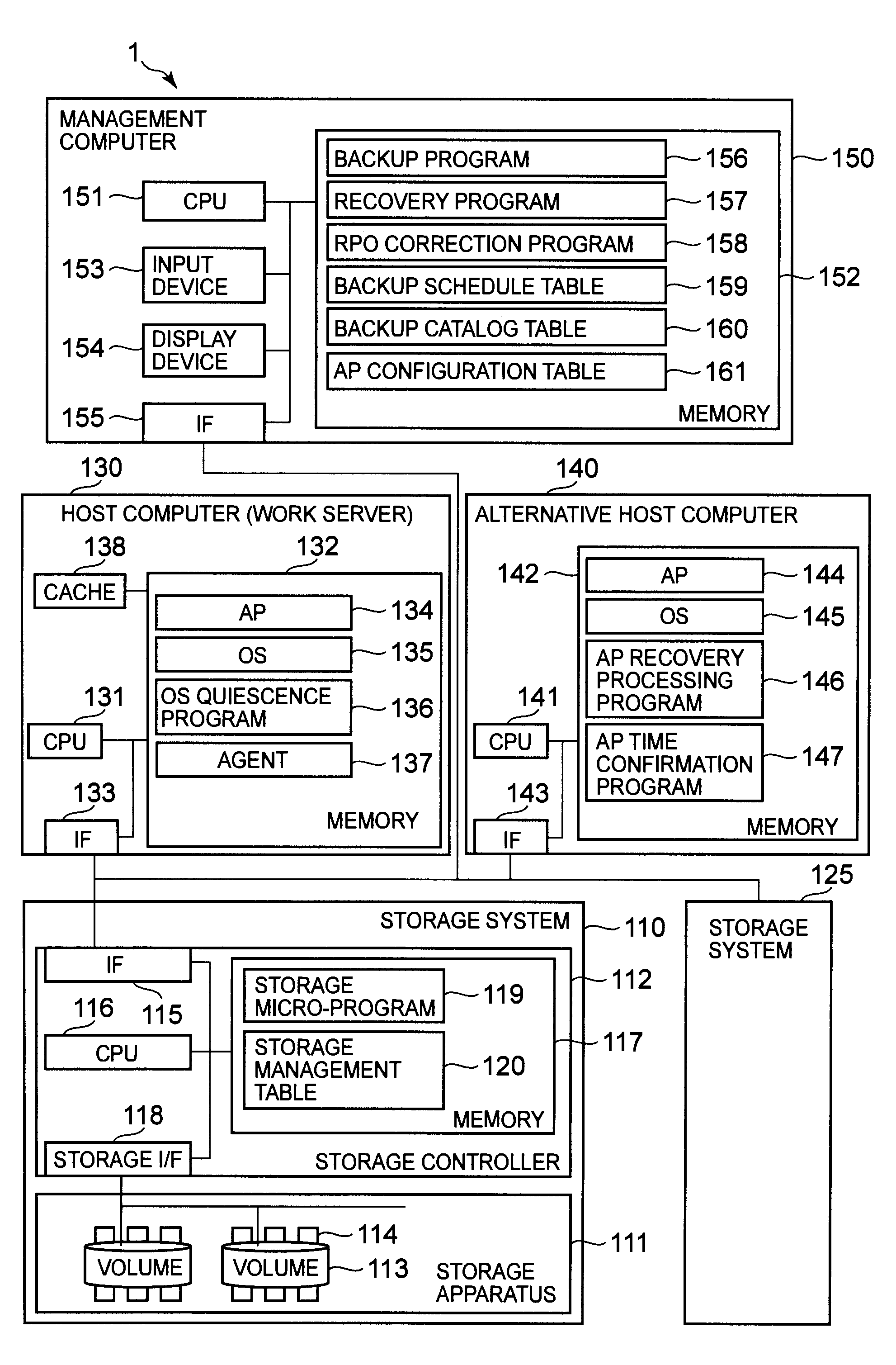
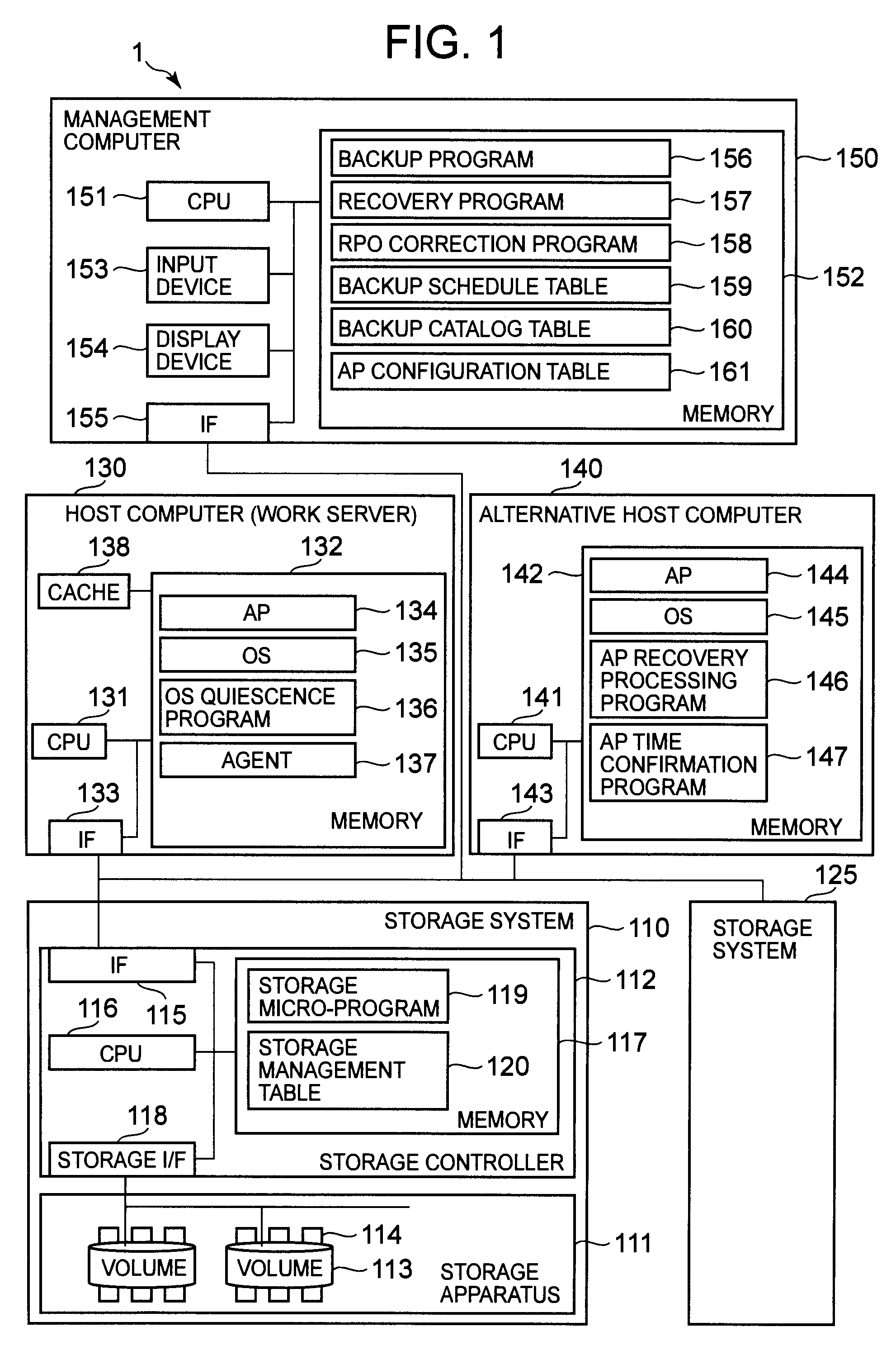
[0043]FIG. 1 is an example of a diagram showing the configuration of a computer system related to the first embodiment of the present invention.

[0044]The computer system 1 of the first embodiment is configured from a storage system 110; a host computer (work server) 130; an alternative host computer 140; and a management computer 150. In the first embodiment, in addition to the storage system 110, one or more storage system 125 is coupled to the host computer (work server) 130, the alternative host computer 140 and the management computer 150. However, the computer system 1 is not limited to this storage system configuration. The computer system 1 may be configured by at least one or more storage systems. Furthermore, the computer system 1 of the first embodiment is configured such that the host computer 130 and the management computer 150 are individual computers. However, the present invention ...

second embodiment

[0132]Next, a second embodiment of the present invention will be explained. This embodiment differs from the first embodiment in that the storage system included in the computer system comprises a NAS (Network Attached Storage). In this embodiment, a case in which the present invention is applied to the backup management of a volume used by an AP under NAS conditions will be explained by focusing on the differences with the configuration of FIG. 1.

[0133]A NAS OS is stored in the memory 1416 of the NAS 1413 of the storage system, and the NAS 1413 functions as a file server.

[0134]FIG. 14 shows an example of a system block diagram of a computer system 1′ comprising a NAS 1413 related to this embodiment. As shown in FIG. 14, the computer system 1′ of this embodiment is configured from a storage system 1410; a host computer 130; an alternative host computer 140; and a management computer 150 the same as the computer system 1 of FIG. 1. The storage system 1410, which differs from that of ...

third embodiment

[0153]A third embodiment differs from the first embodiment in that a virtual server (VM) is constructed in the host computer of the computer system. That is, in the third embodiment, there is described an AP backup method that is executed in accordance with the virtual server (VM).

[0154]FIG. 16 shows an example of a system block diagram of a computer system 1″ of this embodiment. As shown in FIG. 16, the computer system of this embodiment is configured from a storage system 110; a host computer 1530; an alternative host computer 1545; and a management computer 150 the same as FIG. 1. The host computer 1530 and alternative host computer 1545, which differ from FIG. 1, will be explained below.

[0155]The host computer 1530 is configured from a CPU 1531; a memory 1532; and an I / F 1533.

[0156]The CPU 1531 is a processor for executing a program stored in the memory 1532.

[0157]The memory 1532 stores a virtual server (VM) 1534, a virtual server control program 1535, a virtual server quiescenc...


PUM


Abstract

The present invention provides a backup method that makes it possible to specify the recovery-enabled time of an application even in a case where a backup has been performed without staticizing the application. In response to a first instruction from a management computer, a storage system backs up a first volume to a second volume at a first time while a first host computer continues to process an application. In response to a second instruction from the management computer, a second host computer reads out the data of the second volume and acquires a second time that is the time at which the application is recovery-enabled. The management computer stores the relationship between the backup and the second time in backup catalog information.

Description

CROSS-REFERENCE TO RELATED APPLICATIONS[0001]This application relates to and claims priority from Japanese Patent Application No. 2009-104645 filed on Apr. 23, 2009, the entire disclosure of which is incorporated herein by reference.BACKGROUND OF THE INVENTION[0002]1. Field of the Invention[0003]The present invention relates to a storage system, and more particularly to a backup method for data used by a computer system application.[0004]2. Description of the Related Art[0005]Data utilized by an application (will be called “AP” hereinafter) in a host computer may be lost in accordance with “a failure of the storage apparatus”, “the destruction of data by a computer virus”, and “user error”. A “backup” for saving this data as a copy is implemented in a storage apparatus in preparation for a case in which this data is lost. When data used by the AP is lost, the storage apparatus executes a “recovery” to recover the backed up data.[0006]There are various methods for backing up data. On...

Claims


Application Information

Patent Timeline
Patent Type & Authority Patents(United States)
IPC IPC(8): G06F7/00G06F17/00G06F13/00G06F13/28
CPCG06F11/1456G06F11/1458G06F11/1461G06F11/1469G06F11/1484
Inventor IRISAWA, MISAKOMAKI, NOBUHIROOKADA, WATARUEMARU, HIRONORI
Owner HITACHI LTD
Why Eureka
Try Eureka