
Pump horn

a technology of pump horn and horn body, which is applied in the field of pump horn, can solve the problems of old-style air horn aerosol and waste of resources and money, and achieve the effect of building a higher pressure in the chamber

Active Publication Date: 2012-06-05
FISHMAN MICHAEL
View PDF26 Cites 1 Cited by
  • Summary
  • Abstract
  • Description
  • Claims
  • Application Information

AI Technical Summary

Benefits of technology

"The patent describes a pump horn that uses a push / pull slide and a suction piece to create a higher pressure that pushes air into a sound producing device. The sound is then amplified and released through an amplifying unit. The pump horn has a diaphragm and an overcap that allows for a tight seal and the attachment of a horn. The push / pull slide is made of metal or plastic and can be extended and inserted into the chamber to create the pressure that makes the horn produce sound. The technical effects of this invention include a loud sound and a durable pump horn that can be easily attached and detached."

Problems solved by technology

However, the old style air horn aerosols have certain disadvantages.
Second after the gas is used up the gas needs to be discarded which is a waste of resources and money.

Method used


Image

  • Pump horn
  • Pump horn
  • Pump horn

Examples


Embodiment Construction

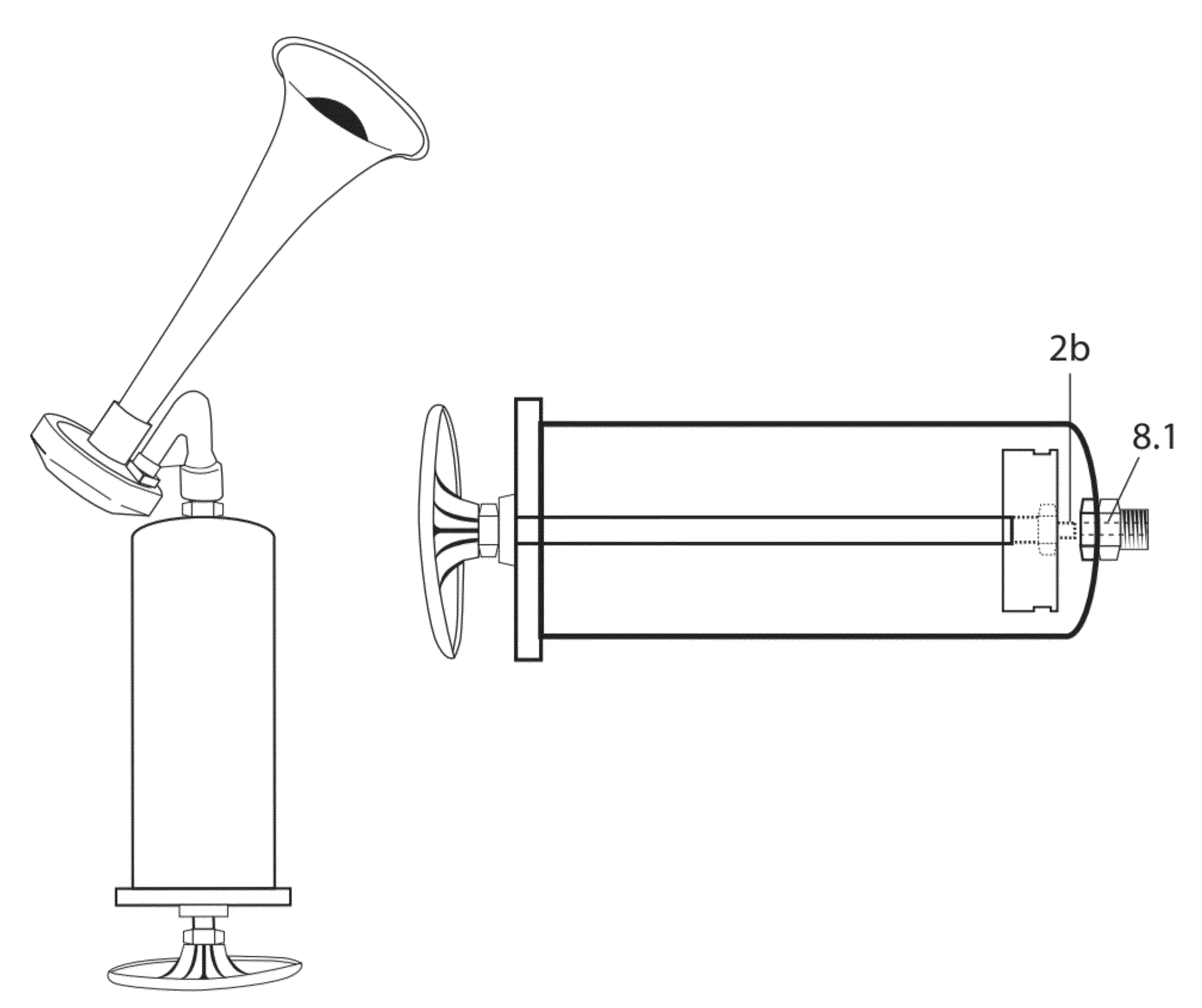
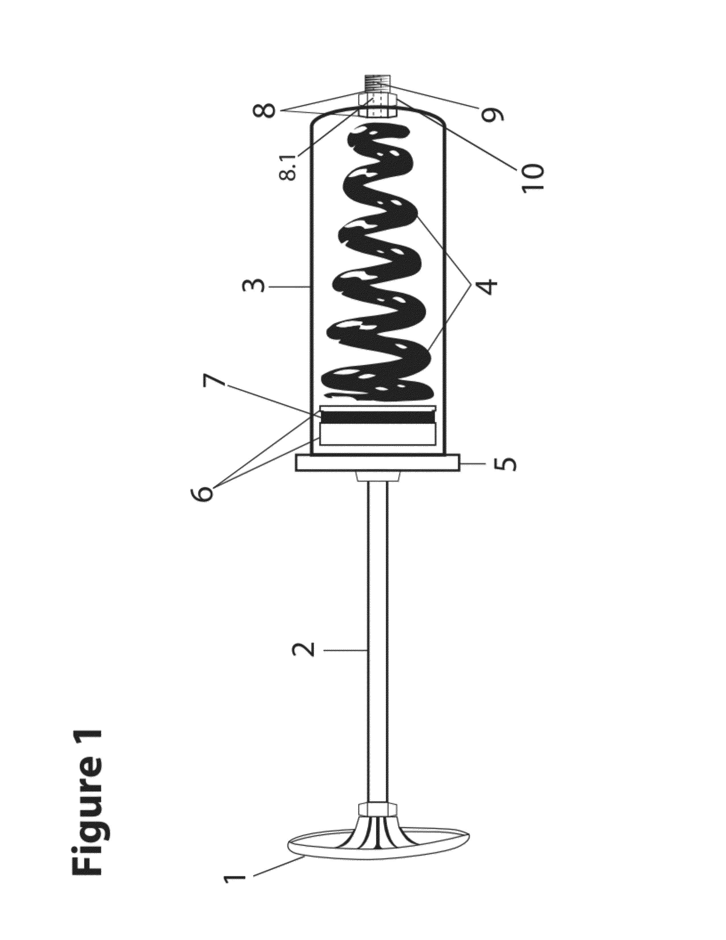
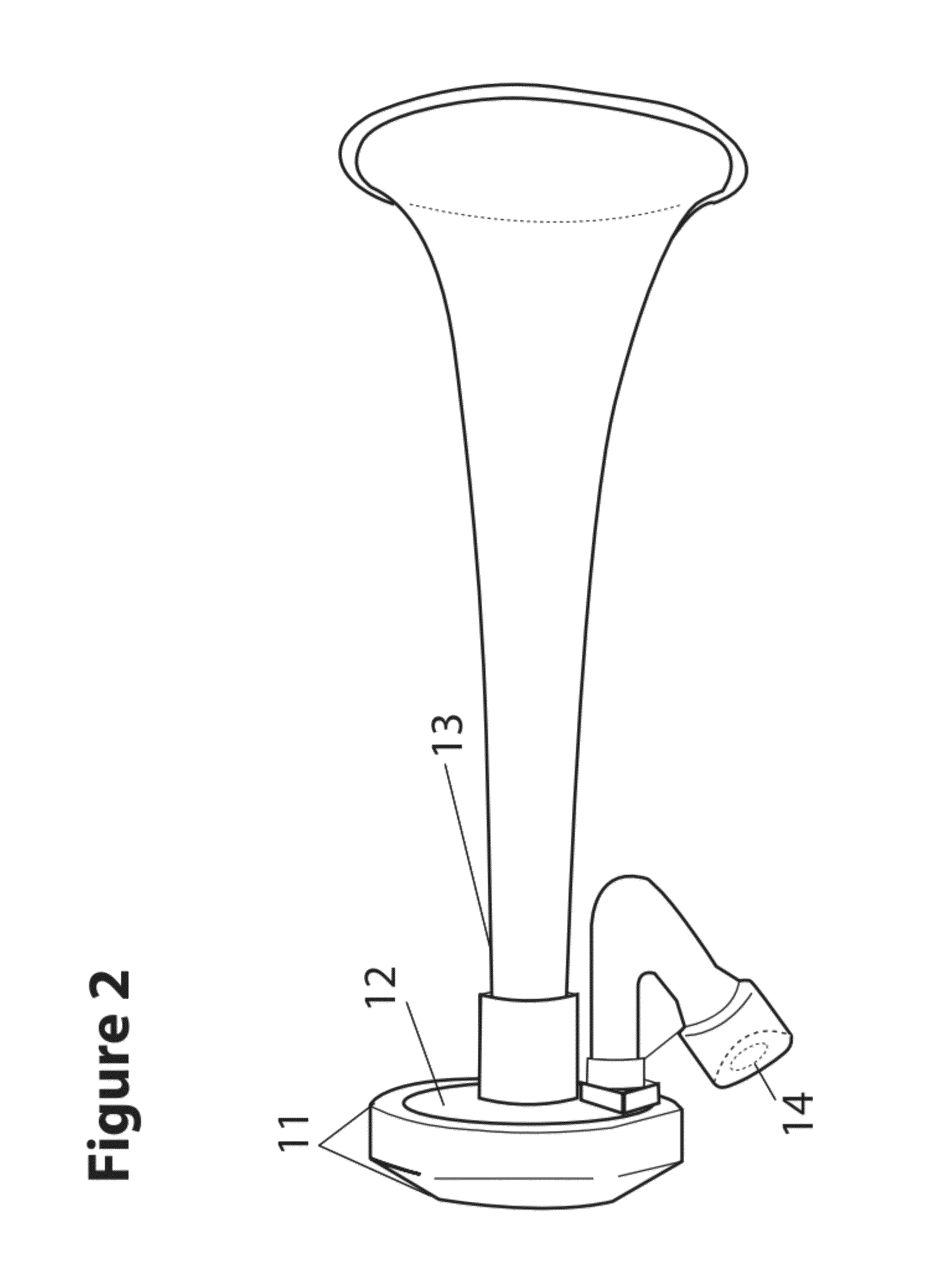
[0021]Referring now to FIG. 1, is a pump of the pump horn, the handle 1 of the FIG. 1 pump in the preferred embodiment is circular, square rectangular and or ergonomically shaped molded plastic, metal, aluminum or rubber. Referring to the handle 1 is attached to the push / pull slide 2 by a screw on nut or glued on securely or molded in plastic to fit on securely. The push / pull slide 2 is made of steel, aluminum or plastic made to be able to slide in and out of the pump and serves as the force to push the air into a horn FIG. 2 which eventually makes the pump horn make its sound. The chamber 3 is made of steel, aluminum, hard plastic or some durable material with holes at both ends to compress air and push out the air at a higher pressure. In this embodiment of the invention the chamber 3 is a circular solid tubular structure about 2¼ inches in diameter steel with a small hole at one end which the attachable member 8 is placed where the horn can be attached. In this embodiment of the ...


PUM


Abstract

The pump horn includes a chamber that can be filled continuously and indefinitely by a push / pull slide that when pushed into the chamber forces pressurized air through an attachable member, a tube, a sound producing device, and an amplifying unit to produce a loud blast sound. The push / pull slide includes a screw in piece at the end which is secureable to the attachable member within the chamber for releasable securement of the push / pull slide. This allows compact carrying and storage.

Description

BACKGROUND[0001]This relates to pump horn specifically to the ease of use, environmentally safe and reusable indefinitely manual powered air horn unit. The invention consists of a chamber that can be filled continuously and indefinitely by a push / pull slide attached to a suction piece that exerts pressurized air pushed through a smaller tube creating a higher pressure that goes through the sounding unit and finally through the horn sound producing device making a loud sound.[0002]Traditional air horns have used aerosols to make the sound blasts. However, the old style air horn aerosols have certain disadvantages. First the aerosol air horns are aerosols and put greenhouse gases into the atmosphere. Second after the gas is used up the gas needs to be discarded which is a waste of resources and money.[0003]Our pump horn which is manually operated has the first advantage of never needing greenhouse gases to operate. The second advantage of our pump horn is it can work indefinitely with...

Claims


Application Information

Patent Timeline
Patent Type & Authority Patents(United States)
IPC IPC(8): G10K9/04F04B33/00
CPCG10K9/04
Inventor FISHMAN, MICHAEL
Owner FISHMAN MICHAEL
Learn More