Lug-jaw for electrical joint

a technology for disconnecting assemblies and electrical joints, which is applied in the direction of coupling contact members, coupling device connections, emergency protective devices, etc., can solve the problems of high cost of copper, excessive use of prior-art systems of too many parts, and high cost of copper. , to achieve the effect of less copper, less expensive copper conductors, and less sharp transitions

Active Publication Date: 2012-06-05
SCHNEIDER ELECTRIC USA INC
View PDF7 Cites 4 Cited by
  • Summary
  • Abstract
  • Description
  • Claims
  • Application Information

AI Technical Summary

Benefits of technology

[0004]According to some embodiments of the present invention, in an electrical circuit where an electrical connection needs to be made or broken, a disconnect assembly is placed in the circuit that allows an operator or a device to disconnect the load from the electrical circuit. The disconnect assembly includes a pullout assembly that has metal blades, which provide the electrical path for current between a line and a load connection, that are inserted into blade-receiving extensions and held in place there as the pullout assembly is inserted into or removed from a base assembly to make or break electrical connections. The base assembly includes a lug-jaw connector that is composed of a lug and an adjacent half jaw. The half jaw uses less copper compared to previous designs, which have used a full jaw to make the electrical connection. The half jaw can be secured to the lug through friction or an attachment means such as a screw. The half jaw may resemble a clip such that when the conductive blade is inserted between, and in contact with, the half jaw and the lug, the blade is held securely in place so that current can flow from the line to the load side of the circuit. To break the electrical connection, the pullout assembly is removed manually or automatically so that the conductive blade thereof physically detaches from the lug-jaw connectors. When the disconnect device is removed an open circuit is created between the line and load portions of the circuit and no current can flow. Compared to previous designs, the disconnect assembly of the present invention advantageously uses far fewer parts, less of the expensive copper conductor, and presents fewer sharp transitions at the joints to electrical current, among other benefits.

Problems solved by technology

Copper is expensive.
In addition, in existing designs, numerous parts are required to form the disconnect assembly.
In short, prior-art systems use too many parts and are expensive because they overuse the amount of copper that is needed.
They also present a number of joints, and joints are undesirable because they produce heat due to electrical current crowding at the transitions and reduce the delivery efficiency of the current.

Method used


Image

  • Lug-jaw for electrical joint
  • Lug-jaw for electrical joint
  • Lug-jaw for electrical joint

Examples


Embodiment Construction

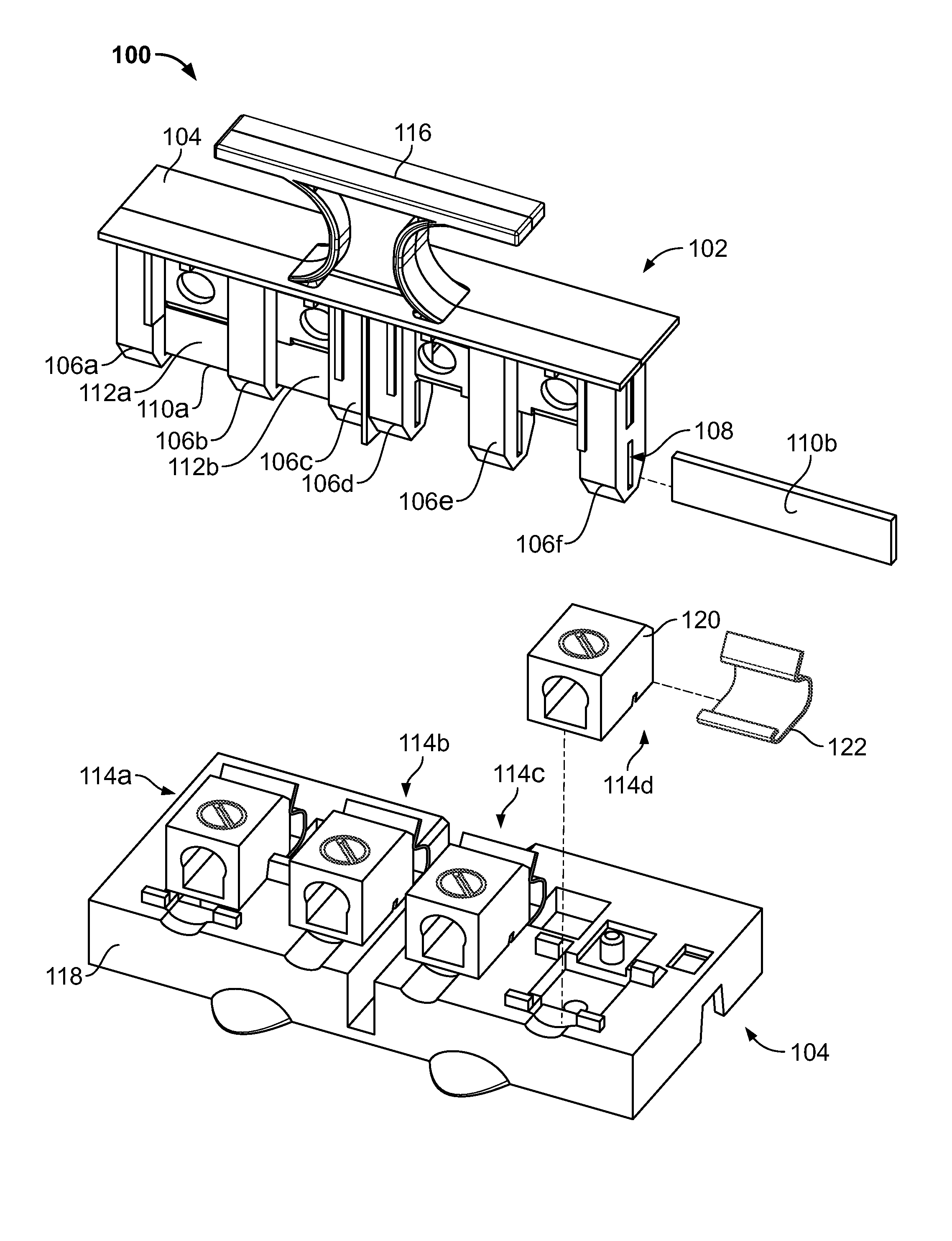
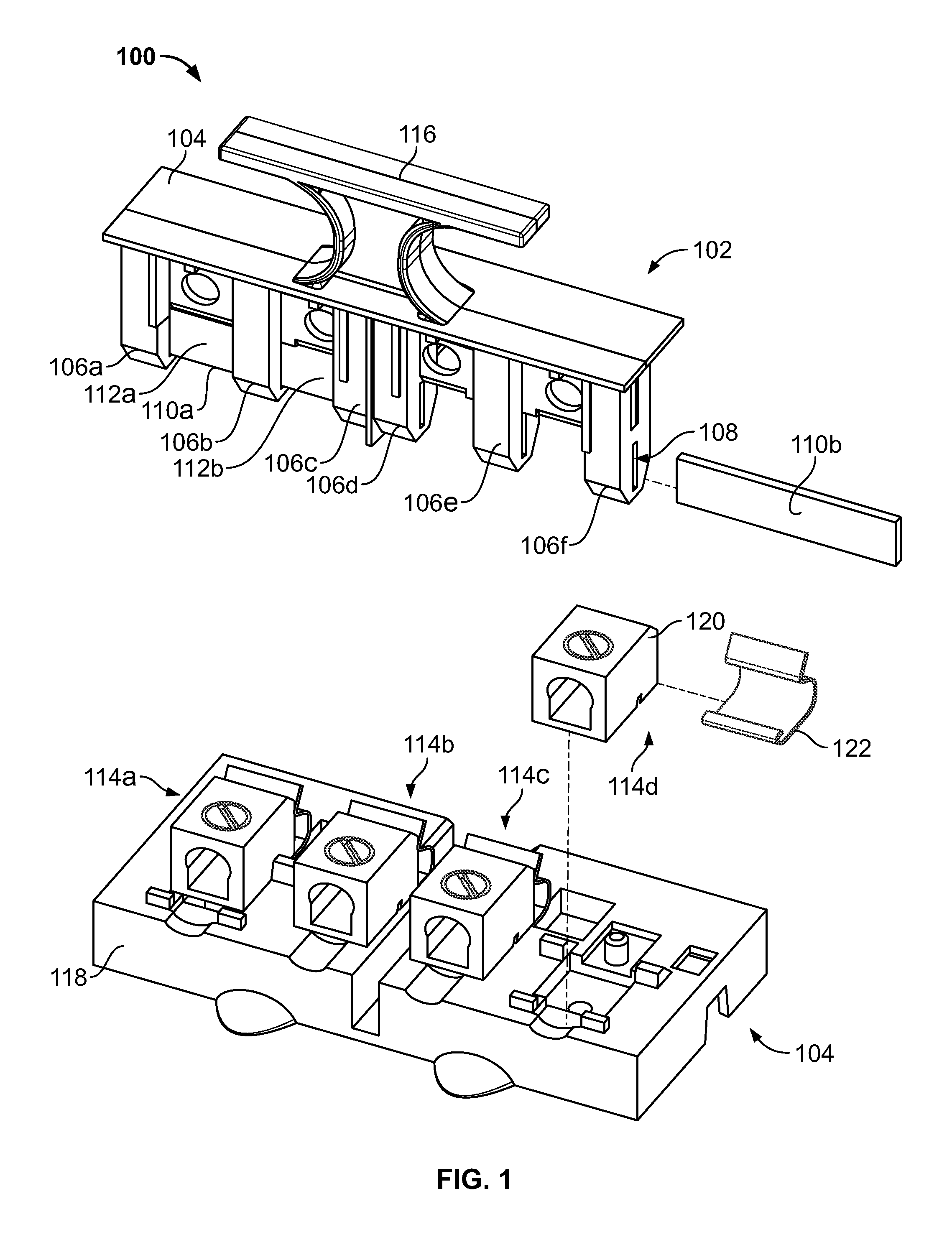
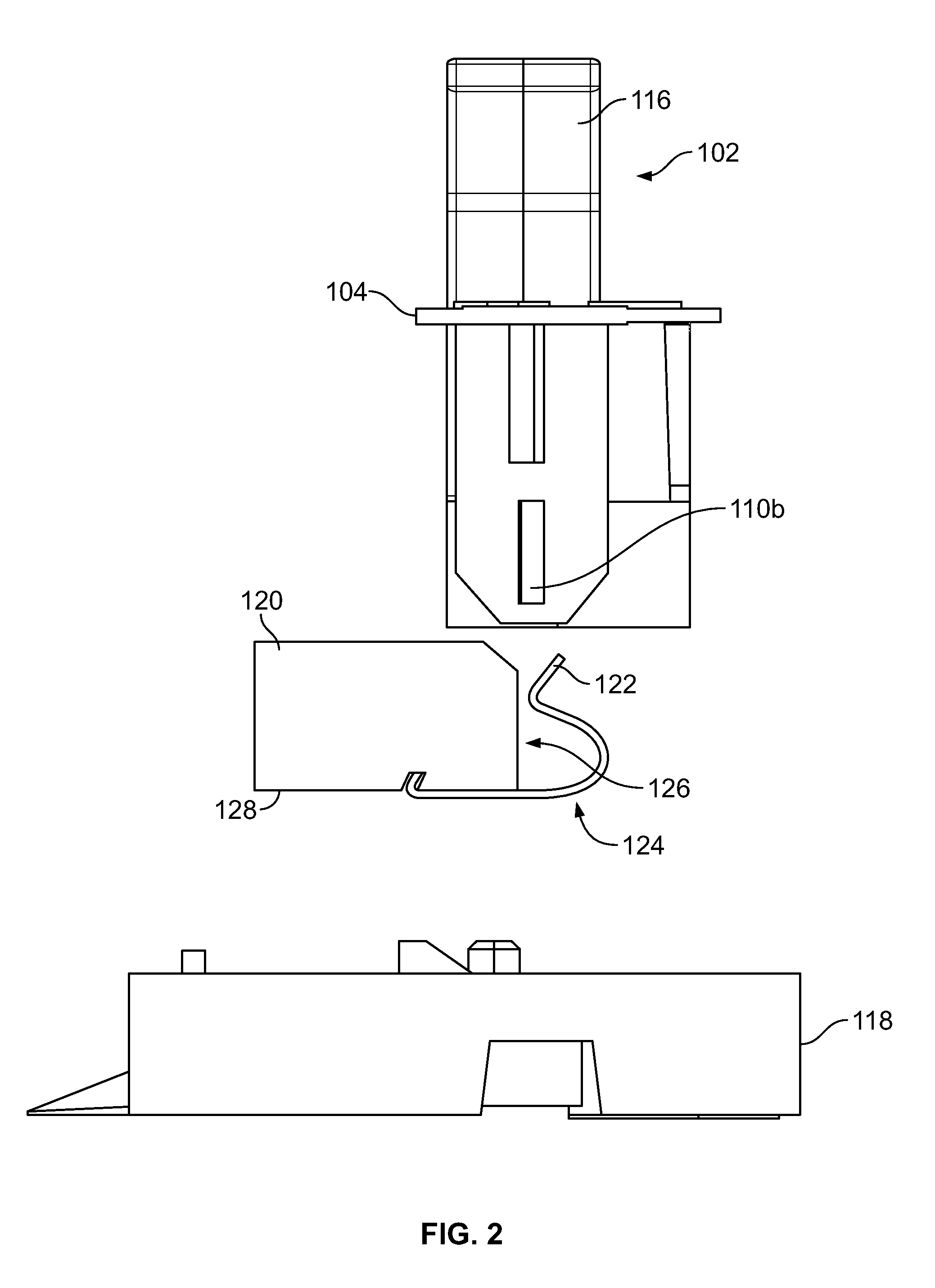
[0014]FIG. 1 is a partially exploded, isometric view of a disconnect assembly 100 according to an aspect of the present disclosure, for making and breaking an electrical connection to an electrical circuit (not shown) to which the assembly 100 is connected. The assembly 100 includes a pullout assembly 102 and a base assembly 104. The pullout assembly 102 is composed of a non-electrically conductive material, such as plastic, and includes blade-receiving extensions 106a-f that extend away from the face portion 104 as shown. Each of the blade-receiving extensions 106a-f includes a corresponding channel 108 (only one channel is numbered for clarity). The assembly 100 further includes a pair of flat blades 110a, 110b that are slidably received within corresponding channels 108 of the blade-receiving extensions 106. One of the blades 110b is shown removed from the channels 108 of the blade-receiving extensions 106d-f in FIG. 1 to illustrate how it is slid into the pullout assembly 100 vi...


PUM


Abstract

A disconnect assembly for making and breaking electrical connections to an electrical circuit. The disconnect assembly includes a pullout assembly and a base assembly. The pullout assembly has downwardly facing extensions with slits in them to receive a blade that is inserted securely through the slits. The exposed portions of the blade are received in corresponding lug-jaw connectors in the base assembly. The lug-jaw connectors have a lug and a half jaw attached to the lug. The half jaw has a curved clip portion that opposes a side surface of the lug such that the exposed portion of the blade is received between the clip portion and the side surface, thereby resulting in minimal use of conductive material for the disconnect assembly.

Description

FIELD OF THE INVENTION[0001]This invention relates generally to disconnect assemblies for electrical joints.BACKGROUND[0002]In known air conditioning disconnect (ACDC) systems, a disconnect assembly has a pullout assembly with conductive jaws separable from “conductive connectors” affixed in a base assembly to conductive lugs. The conductive connectors are bent at a 90 degree angle to receive the respective conductive jaws. The pull out assembly includes a full jaw connected to a handle. The base assembly includes a lug that is secured to a base of the base assembly and a corresponding conductive connector. In the conductive position the conductive connectors of the base assembly are mated to a pair of the full jaws of the pullout assembly, allowing current to flow from one lug, which receives line current, across the pair of full jaws, to another lug, which provides the line current to the air conditioning load. The full jaw includes two pieces of copper that are bent to form a jaw...

Claims


Application Information

Patent Timeline
Patent Type & Authority Patents(United States)
IPC IPC(8): H01H9/00
CPCH01R4/4809H01R13/04H01R13/703
Inventor ABROY, HAMID S.
Owner SCHNEIDER ELECTRIC USA INC
Why Eureka
Try Eureka