Core for electrical machine

a technology of transverse flux and core, which is applied in the direction of dynamo-electric components, synchronous machines with stationary armatures and rotating magnets, magnetic circuit shapes/forms/construction, etc., and can solve the problems of eddy currents, eddy currents are a source of energy loss, and the core housing is not laminated, and the manufacturing process is complicated

Active Publication Date: 2017-01-26
EOCYCLE TECH
View PDF3 Cites 2 Cited by
  • Summary
  • Abstract
  • Description
  • Claims
  • Application Information

AI Technical Summary

Benefits of technology

[0045]Generally, an object of the invention, in accordance with at least one embodiment thereof, provides a laminated core for assembly in a TFEM that minimizes the eddy current therein.
[0049]An object of the invention, in accordance with at least one embodiment thereof, provides a more efficient laminated core that allows for a smaller coil in the TFEM that requires less copper thereof.
[0050]An object of the invention, in accordance with at least one embodiment thereof, provides a laminated core that avoids a lamination of independent sheets stack that has to be bent with different radiuses to achieve a symmetrical sheet stack for the two core poles to have a pole pitch separation distance.

Problems solved by technology

The current flowing through the resistance of the conductor also dissipates energy as heat in the material hence having an adverse effect on electrical machines efficiency.
Thus eddy currents are a source of energy loss in alternating current (AC) inductors, transformers, electric motors and generators, and other AC machinery, requiring special construction such as laminated magnetic cores to minimize them.
The cores housing, that is not laminated, is also more complex to manufacture and assemble to hold each core stack together during the assembly of the stator and part of the magnetic flux is loss to the housing when the magnetic concentrators are in the unaligned position.
Other detrimental issues are occurring when honing the stator's interior like a separation of the laminated sheets cores.

Method used


Image

  • Core for electrical machine
  • Core for electrical machine
  • Core for electrical machine

Examples


Embodiment Construction

[0070]Our work is now described with reference to the Figures. In the following description, for purposes of explanation, numerous specific details are set forth in order to provide a thorough understanding of the present invention by way of embodiment(s). It may be evident, however, that the present invention may be practiced without these specific details. In other instances, when applicable, well-known structures and devices are shown in block diagram form in order to facilitate describing the present invention.

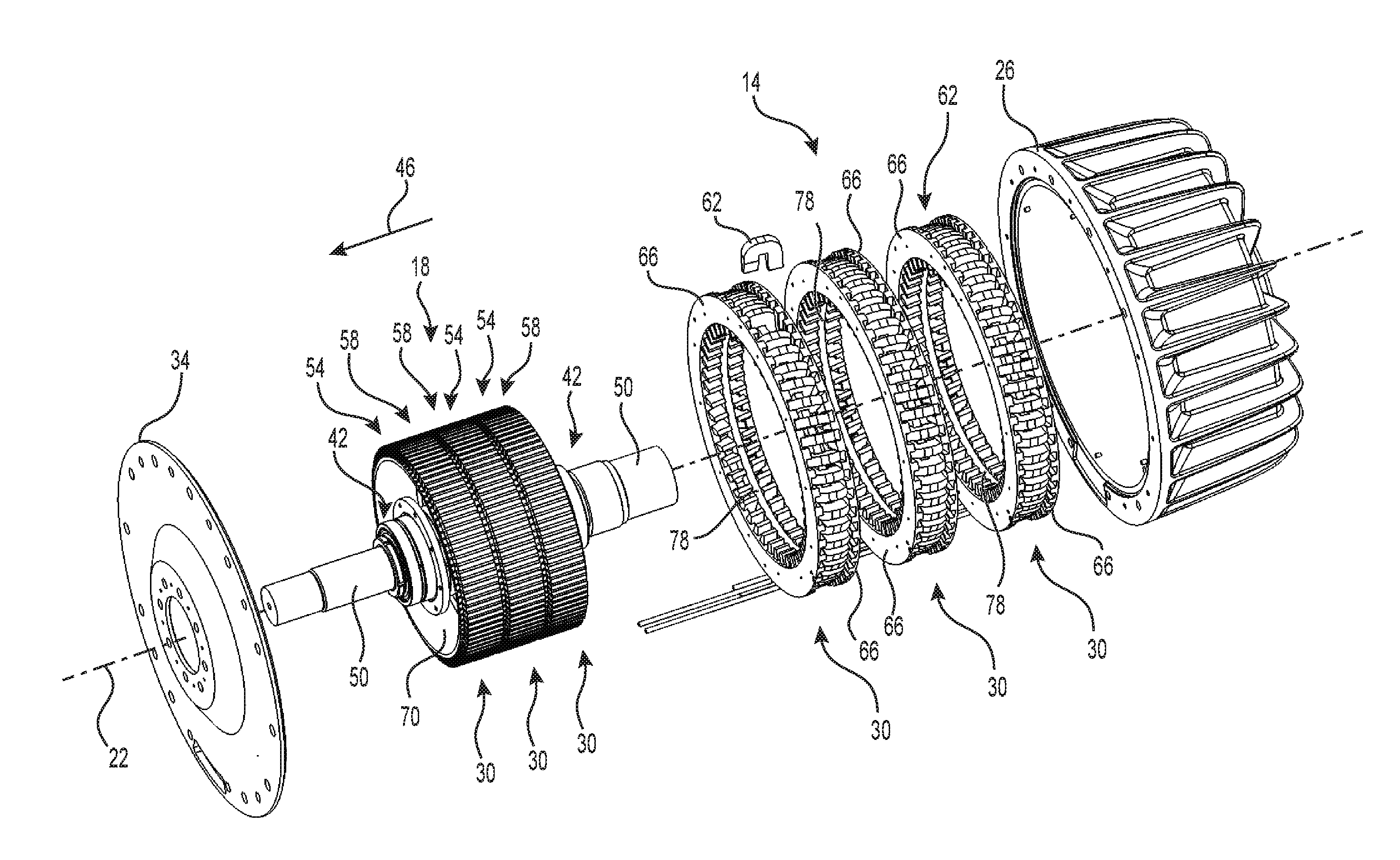
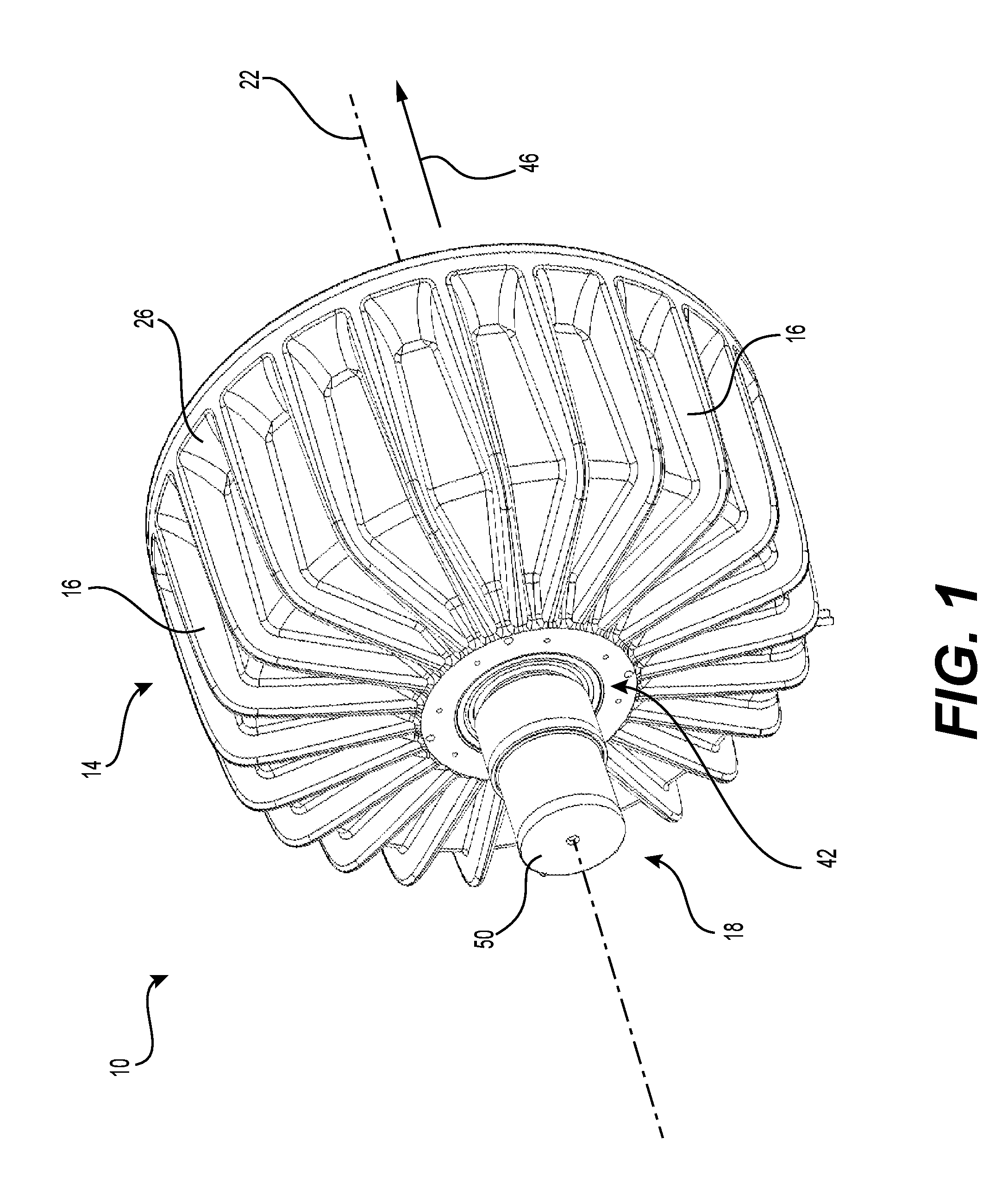
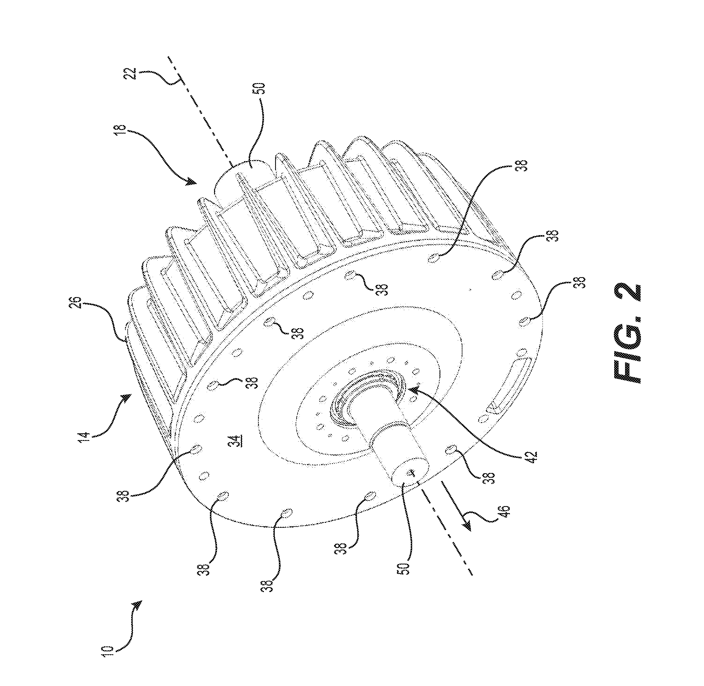
[0071]A TFEM 10 is illustrated in FIG. 1 through FIG. 3. The TFEM 10 includes a stator portion 14 and a rotor portion 18. The stator portion 14 is adapted to remain fixed while the rotor portion 1, located within the stator portion 14, is adapted to rotate in respect with the stator portion 14 about rotation axis 22 thereof. The illustrated stator portion 14 is equipped with an array of fins 16 radially protruding from the housing 26 to help increase the heat exchange betw...


PUM


Abstract

A transverse flux electrical machine comprising a rotor portion and a stator portion is presented, the stator portion comprising a plurality of cores for use in conjunction with the rotor, each of the plurality of cores comprising a plurality of ferromagnetic sheet material layers substantially bent in a “U” configuration and stacked one on top of the other, a surface of each sheet material layer being substantially parallel with a core axis of the “U” configuration for reducing eddy currents therein and a pair of legs including, respectively, a reduction portion along the legs, toward a pair of poles thereof.

Description

CROSS-REFERENCES[0001]The present invention relates to, claims priority from and is a division application of United States Patent Provisional Application No.: 62 / 194,352, filed, Jul. 20, 2015, entitled C-CORE FOR ELECTRICAL MACHINE, this document is incorporated herein by reference in its entirety.BACKGROUND OF THE INVENTION[0002]1. Field of the Invention[0003]This invention relates generally to transverse flux electrical machines. The present invention more specifically relates to a core for transverse flux alternators and assembly thereof.[0004]2. Description of the Related Art[0005]Alternators and motors are used in a variety of machines and apparatuses to produce electricity from mechanical movements. They find applications for energy production and transportation, to name a few. Alternators and motors can use Transverse Flux Permanent Magnet (TFPM) technologies.[0006]Transverse flux machines with permanent magnet excitation are known from the literature, such as the dissertati...

Claims


Application Information

Patent Timeline
Patent Type & Authority Applications(United States)
IPC IPC(8): H02K1/12H02K1/27H02K1/04H02K21/12
CPCH02K1/12H02K1/04H02K1/2706H02K21/12
Inventor TREMBLAY-SIMARD, RAPHAELNADEAU, RAPHAELFORTIN, PATRICE
Owner EOCYCLE TECH
Why Eureka
Try Eureka