Fuel injector having segmented metal core

Inactive Publication Date: 2005-05-17
ROBERT BOSCH GMBH
View PDF27 Cites 15 Cited by
  • Summary
  • Abstract
  • Description
  • Claims
  • Application Information

AI Technical Summary

Benefits of technology

[0013]The present invention minimizes the eddy currents by providing an electr

Problems solved by technology

Prior art fuel injectors have induced eddy currents, which are detrimental to the perfo

Method used


Image

  • Fuel injector having segmented metal core
  • Fuel injector having segmented metal core
  • Fuel injector having segmented metal core

Examples


Embodiment Construction

)

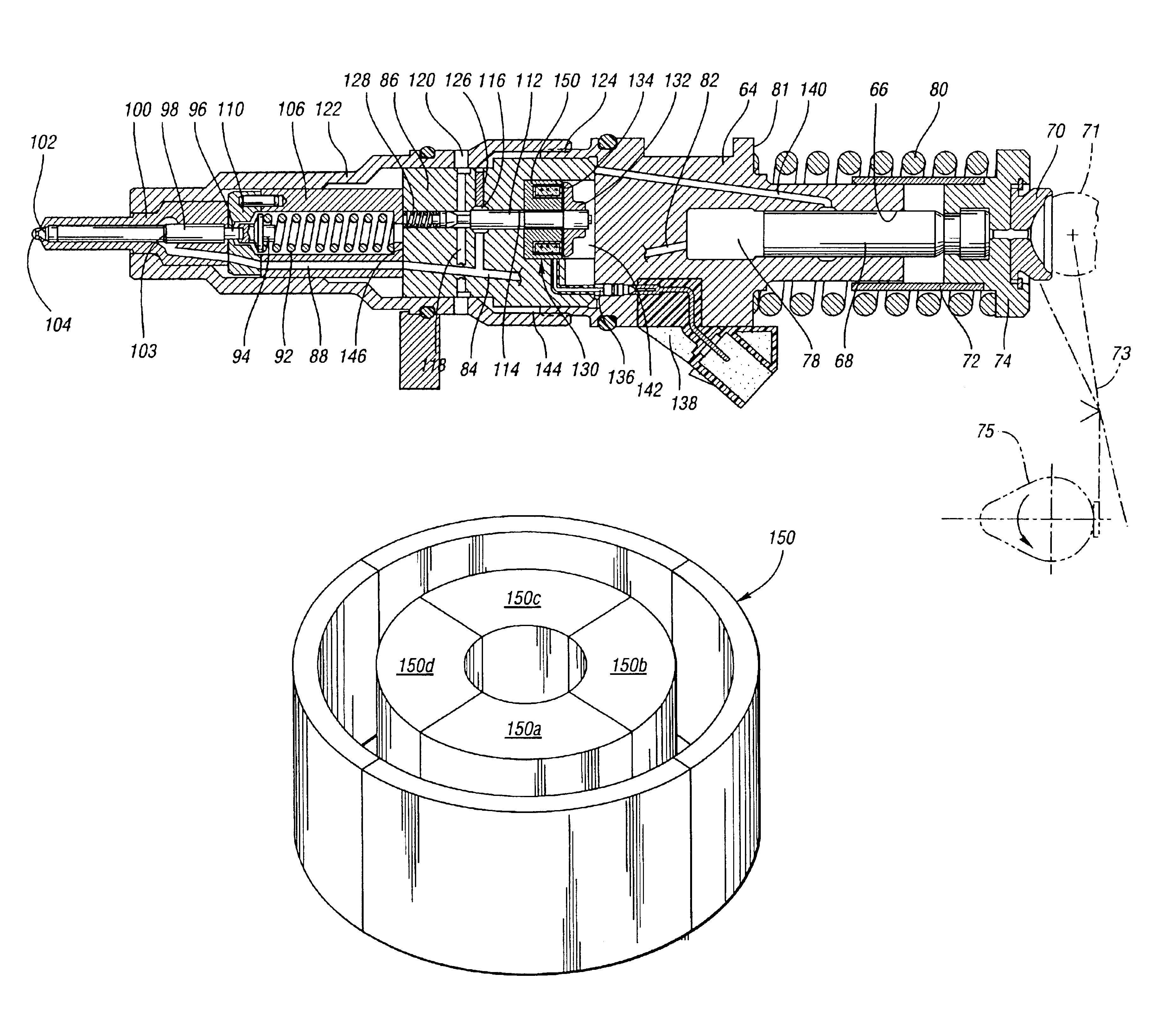
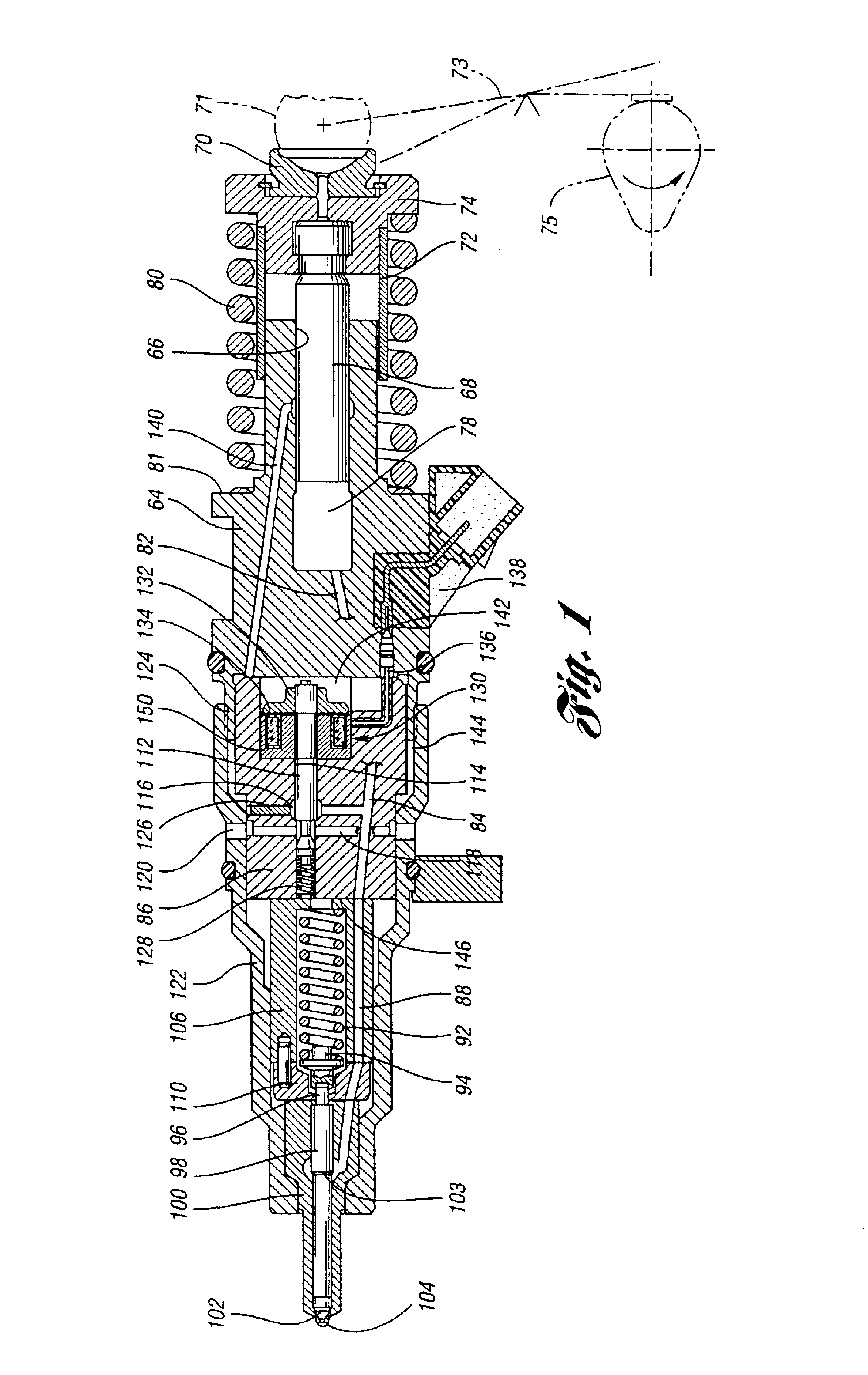
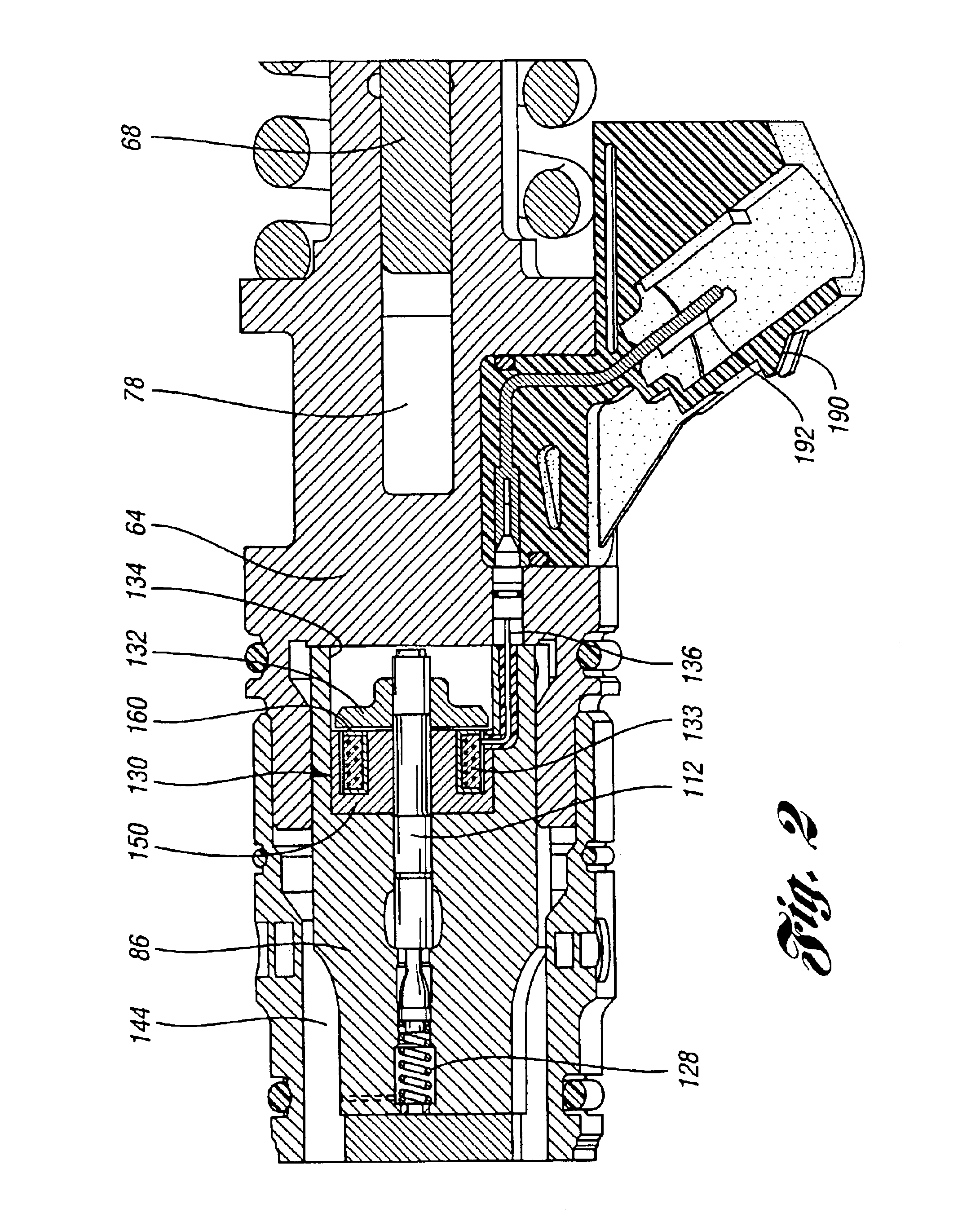
[0018]Referring now to the drawings, the injector assembly of the present invention includes a relatively small pump body 64. A central pumping cylinder 66 in body 64 receives plunger 68. A cam follower assembly 70 includes a follower sleeve 72 and a spring seat 74. The follower assembly 70 is connected to the outer end of plunger 68. The cylinder 66 and plunger 68 define a high-pressure cavity 78. The plunger is urged normally to an outward position by plunger spring 80, which is seated on the spring seat 74 at the outer end of the plunger. The inner end of the spring is seated on a spring seat shoulder 81 of the pump body 64.

[0019]The cam follower 70 is engageable with a surface 71 of an actuator assembly shown at 73, which is driven by engine camshaft 75 in known fashion. The stroking of the piston creates pumping pressure in chamber 78, which is distributed through an internal passage 82 formed in the lower end of the body 64. This passage communicates with the high-pressure pa...


PUM


Abstract

An electromagnetic actuator for a fluid pressure control valve in a fuel injector for an internal combustion engine is disclosed. The fuel injector comprises a control module including a fuel pressure control valve; an armature connected to the fuel pressure control valve; and a stator assembly including a magnetic core comprising of at least two segments and a bobbin. The stator assembly, when it is energized by a power source, produces a magnetic field to draw the armature towards the stator assembly.

Description

BACKGROUND OF THE INVENTION[0001]1. Field of the Invention[0002]The invention relates to a segmented metal core for an electromagnetic actuator for a control valve of a fuel injector for an internal combustion engine.[0003]2. Background Art[0004]Co-pending patent application Ser. No. 10 / 208,587, entitled “Fuel Injector For Diesel Engines”, filed by W. Scott Fischer, David Eickholt and Mike Weston on Jul. 30, 2002, now U.S. Patent 6,758,415, which is assigned to the assignee of the present application, discloses an injector assembly for an internal combustion engine, wherein the control valve and valve actuator are formed as a module that is independent of the pump body and the nozzle assembly. The module, the plunger body and the nozzle assembly are arranged in a linear, stacked relationship. The co-pending application is assigned to the assignee of the present invention.[0005]The control valve in the fuel injector of the co-pending application is closed by applying a voltage to a m...

Claims


Application Information

Patent Timeline
IPC IPC(8): F02M57/00F02M57/02F02M59/00F02M59/36F02M59/46F02M59/20H01F7/08H01F7/16H01F3/00
CPCF02M57/023F02M59/366H01F7/1638H01F7/081F02M59/466H01F3/00
Inventor NUSSIO, RANDY
Owner ROBERT BOSCH GMBH
Why Eureka
Try Eureka