
Shower bar assembly

a technology of showering bar and assembly, which is applied in the direction of curtain suspension devices, machine supports, other domestic objects, etc., can solve the problems of limited water spraying out of the enclosure, undesirable mess, and other than straight bars, and achieve the effect of expanding the usable spa

Active Publication Date: 2012-07-10
KENNEY MFG
View PDF10 Cites 35 Cited by
  • Summary
  • Abstract
  • Description
  • Claims
  • Application Information

AI Technical Summary

Benefits of technology

"The present invention is a shower bar assembly that solves the problem of limited space in shower stalls. It includes mounting brackets that are attached to the wall of the shower stall and a tubular shower bar that is suspended between the mounting brackets. The shower bar can be fixed in a rotational position, making it more convenient for users. The assembly requires minimal tools and training to install. Overall, the invention expands the usable space in the shower stall and provides a more convenient and easy-to-use shower bar."

Problems solved by technology

In defining such enclosures, splashing water out of the enclosure is limited by the use of a sliding door, typically a translucent plastic or shatter proof glass, or more conveniently, a shower curtain supported by a shower bar or rod.
However, creating a shower bar that is other than a straight bar creates its own new problems.
In particular, the bar cannot be allowed to rotate within its mounting brackets or the desired expanded area would be compressed and water from the shower spray may exit the enclosure creating an undesirable mess.
In particular, because many homeowners maintain their own households, they require a shower bar assembly that can be installed with few or only basic tools and with minimal skill.

Method used


Image

  • Shower bar assembly
  • Shower bar assembly
  • Shower bar assembly

Examples


Embodiment Construction

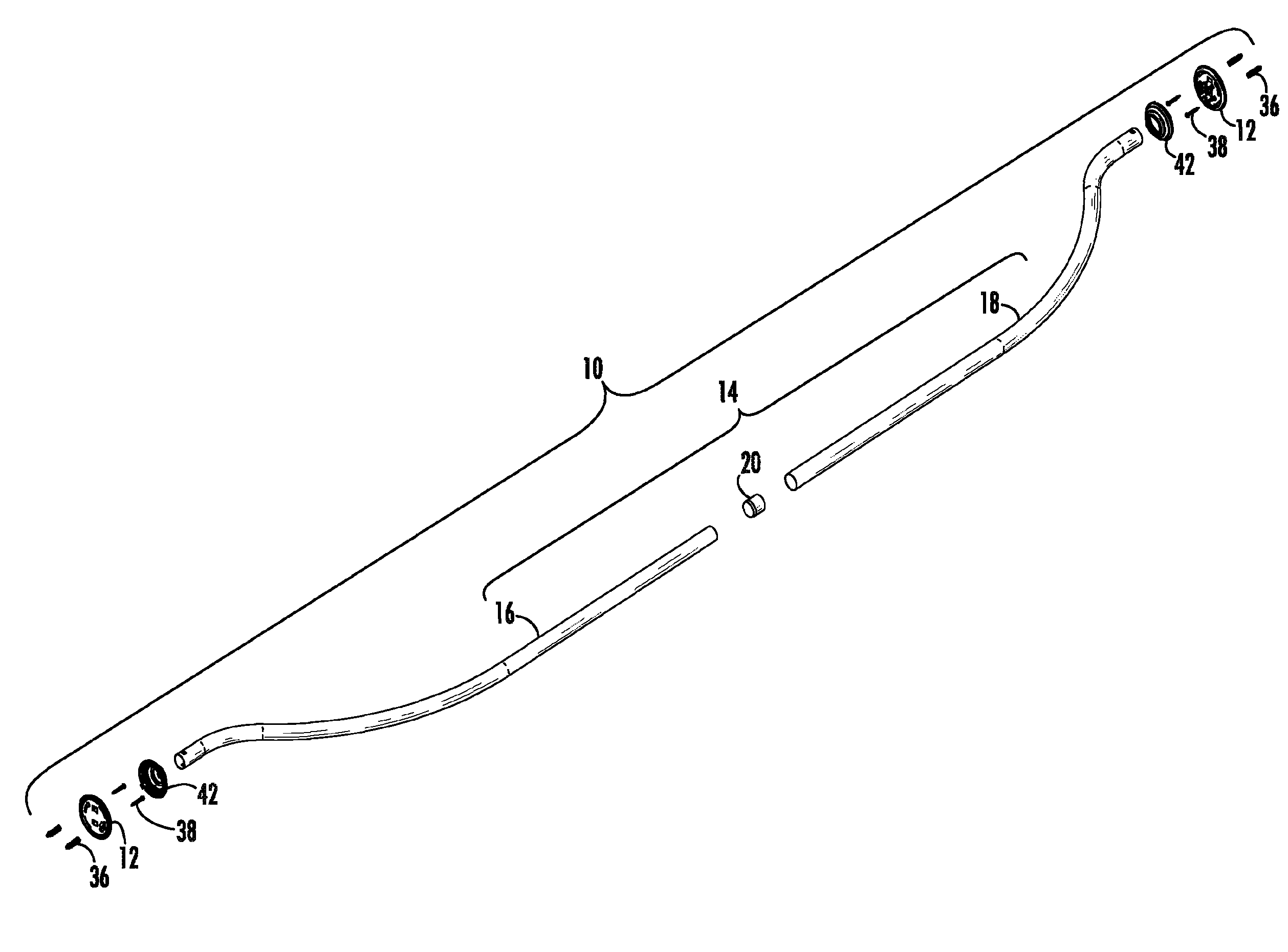
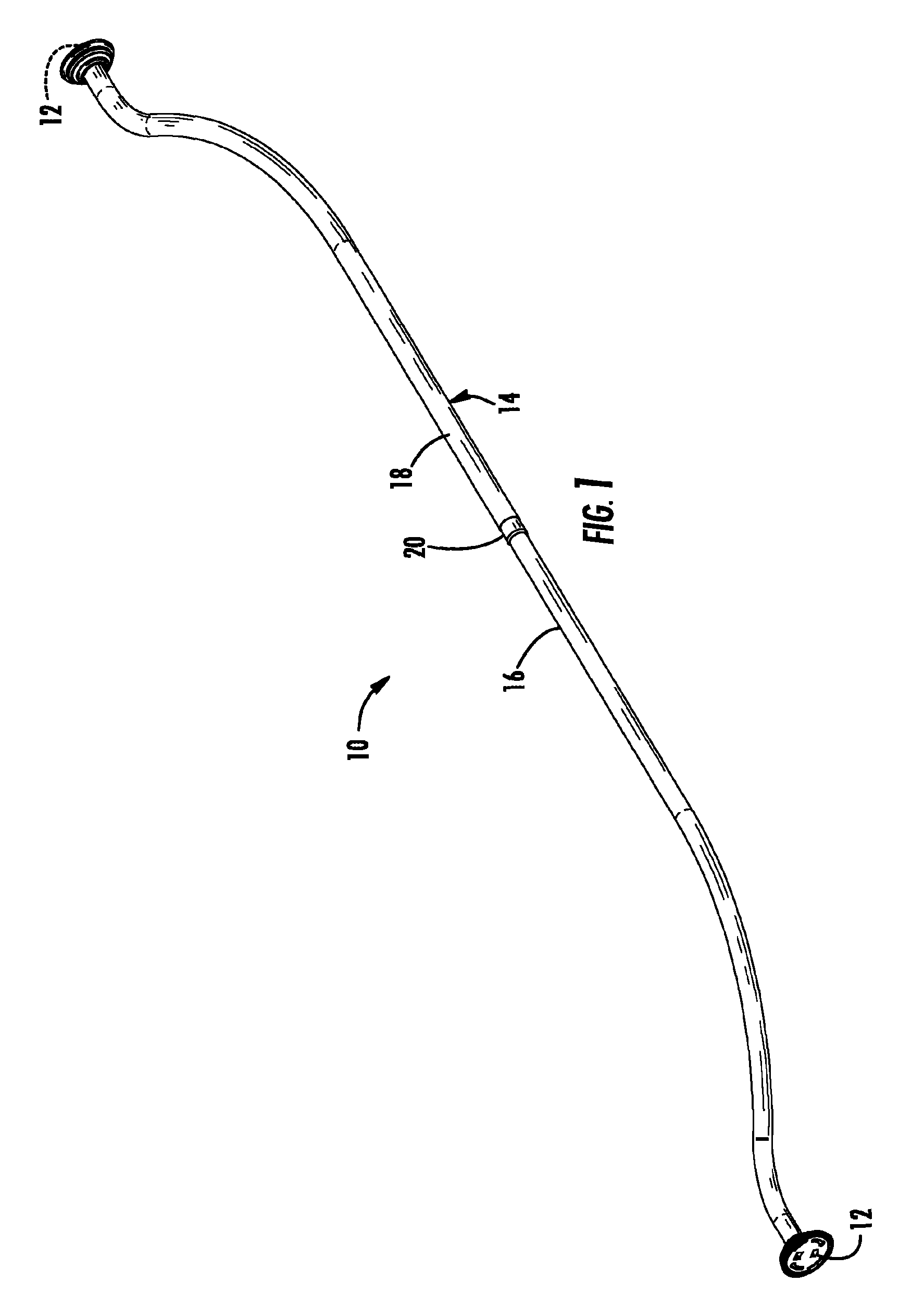
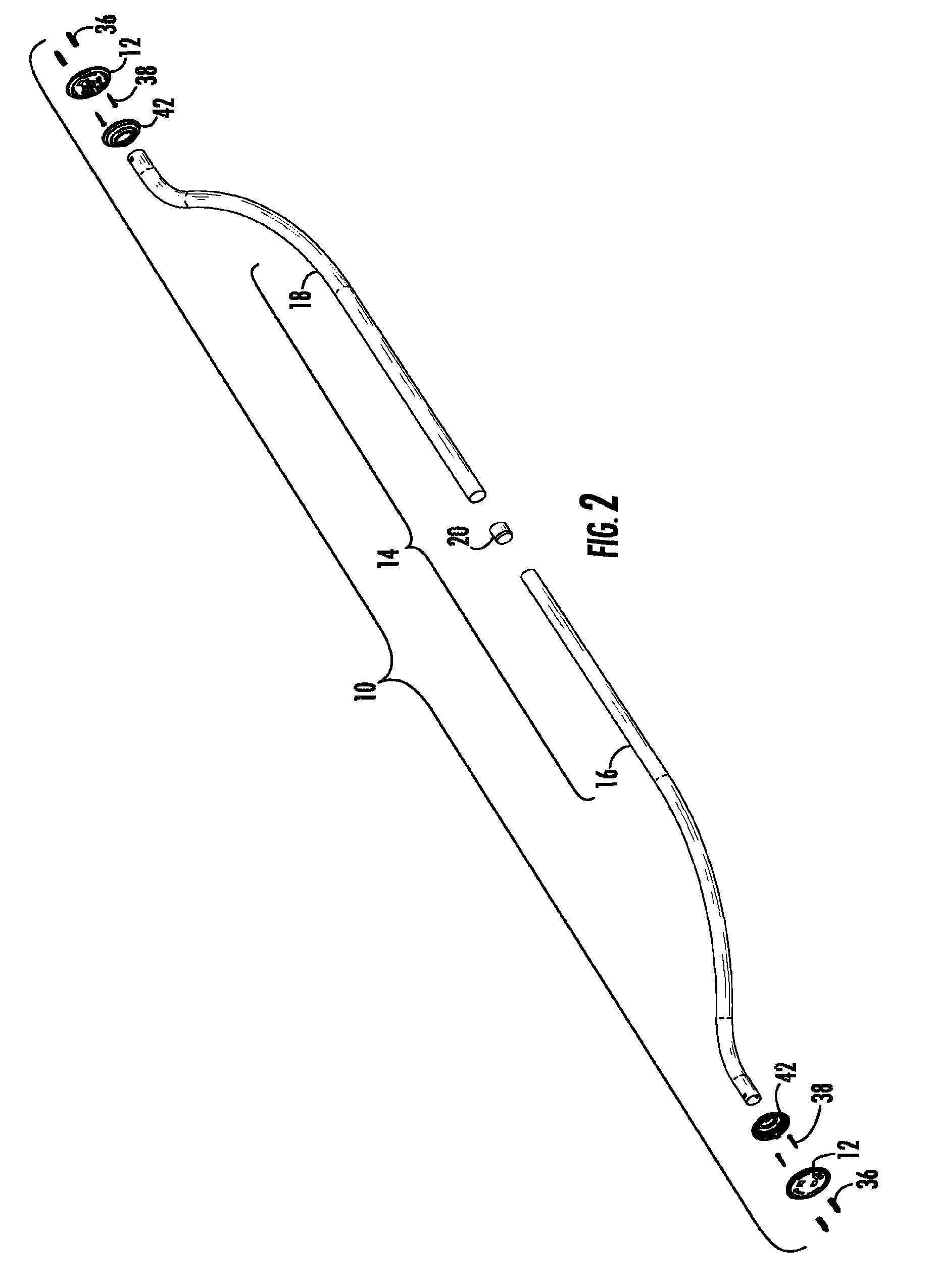
[0026]Referring to FIGS. 1 and 2, the shower bar assembly of the present invention is shown generally at 10. As will be described in greater detail below, the shower bar assembly of the present invention includes a pair of mounting brackets 12 configured and arranged to be mounted to a wall of a shower stall. A tubular shower bar 14 is suspended between the mounting brackets 12 and is preferably telescopically adjustable.

[0027]Specifically, the tubular shower bar portion 14 is preferably formed from two halves 16, 18 that may couple together to allow the overall length of the shower bar 14 to be adjusted telescopically to the desired size. Although a cylindrical shower bar is preferred, any tubular shape may be used. A compression fitting 20 is provided to fix the shower bar at the desired length. The shower bar portion 14 has “S”-shaped ends to enable the shower bar 14 to expand the usable space within the shower stall. Although S-shaped ends are shown, other configurations could b...


PUM


Abstract

A shower bar assembly that includes a pair of mounting brackets configured and arranged to be mounted to a wall of a shower stall is disclosed. Each of the mounting brackets has a base portion with a first shelf and a second shelf projecting from the base portion. The first and second shelves each have a retaining peg projecting from each shelf, respectively. A tubular shower bar is included and has two opposing ends. Each of the ends of the tubular shower bar has a pair of surfaces in which each defines an aperture through the tubular shower bar. Each end of the tubular shower bar is configured and arranged to slide onto the first and second shelves of the mounting brackets, with the apertures interlocking with each of the retaining pegs, respectively, to suspend the shower bar between the mounting brackets and to prevent the shower bar from rotating between the brackets.

Description

BACKGROUND OF THE INVENTION[0001]1. Field of the Invention[0002]The present invention relates generally to shower bar assemblies and more particularly to a kit for mounting a shower bar in a shower stall to expand the usable space within a shower stall in a secure manner.[0003]2. Background of the Related Art[0004]In the construction of most bathrooms, it is common to position a shower nozzle mounted on the wall at an enclosure above a bath tub to thereby provide the option of a shower for the resident using the bathroom facility. In defining such enclosures, splashing water out of the enclosure is limited by the use of a sliding door, typically a translucent plastic or shatter proof glass, or more conveniently, a shower curtain supported by a shower bar or rod. The shower curtain is ordinarily constructed and arranged to drape loosely from a set of eyelets or curtain rings, which slide along the shower bar. A set of such rings is normally mounted slidably on the shower bar, which i...

Claims


Application Information

Patent Timeline
Patent Type & Authority Patents(United States)
IPC IPC(8): A47K3/00
CPCA47K3/38
Inventor HANLEY, MICHAELLABARRE, LEO E.VOAS, SALLY
Owner KENNEY MFG
Learn More