
Television viewer interface system

a viewer interface and television technology, applied in the field of interactive display of viewer information, can solve the problems of difficult to use and understand vcrs, multimedia equipment manufacturers do not use a consistent user interface, counters are not intuitive to the majority of the general public, and achieve high-resolution graphics

Inactive Publication Date: 2012-07-10
TIVO SOLUTIONS INC
View PDF59 Cites 80 Cited by
  • Summary
  • Abstract
  • Description
  • Claims
  • Application Information

AI Technical Summary

Benefits of technology

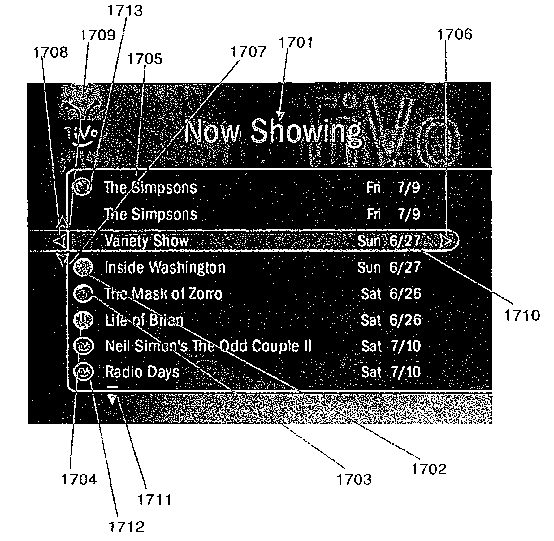
[0014]The invention provides a television viewer interface system. The system provides an intuitive, visually communicative user interface. In addition, the invention provides a system that allows menu creators to produce a visually pleasing menu system that is efficient, yet offers high resolution graphics.
[0015]An embodiment of the invention provides a viewer interface that allows the viewer to access different functions of a system. The invention's construct allows items called video loopsets to be stored on a storage device. A video loopset is a three to four second loop of video created so that the ending and beginning seamlessly merge together to give the effect of a continuous video stream as the system plays the loopset from beginning to end, looping back to the beginning of the loopset each time the end is reached.

Problems solved by technology

The most common complaint (and joke) is that VCRs, in particular, are difficult to use and understand.
This complaint is typical of the majority of multimedia devices.
The problem with these approaches are that multimedia equipment manufacturers do not use a consistent user interface.
Further, terms, phrases, and counters are not intuitive to the majority of the general public.
Menus used to guide users through options delivered by the multimedia devices are also confusing and cryptic.
Cursor appearance and movement are rudimentary and the user is easily confused by the non-intuitive uses of menu choices.
The developers try to add a Hollywood flair to the menu layouts, but still fail at effectively communicating information to the user.

Method used


Image

  • Television viewer interface system
  • Television viewer interface system
  • Television viewer interface system

Examples


Embodiment Construction

[0061]The invention is embodied in a television viewer interface system in a computer environment. A system according to the invention provides an intuitive, visually communicative user interface. In addition, the invention provides a system that allows menu creators to produce a visually pleasing menu system that is efficient, yet offers high resolution graphics.

[0062]A preferred embodiment of the invention provides a viewer interface that allows the viewer to access different functions of a system. Video loopsets, highlight bars, and whispering arrows create an visually intuitive atmosphere for the user.

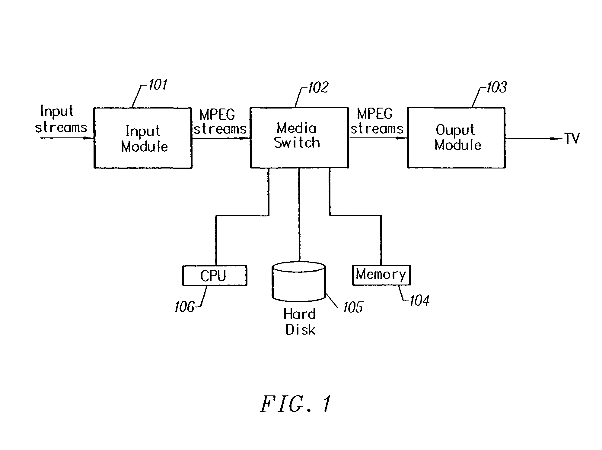
[0063]Referring to FIG. 1, a preferred embodiment of the invention has an Input Section 101, Media Switch 102, and an Output Section 103. The Input Section 101 takes television (TV) input streams in a multitude of forms, for example, National Television Standards Committee (NTSC) or PAL broadcast, and digital forms such as Digital Satellite System (DSS), Digital Broadcast Services ...


PUM

PropertyMeasurementUnit
timeaaaaaaaaaa
timeaaaaaaaaaa
timeaaaaaaaaaa

Abstract

A television viewer interface system provides a viewer interface that allows the viewer to access different functions of a system. A highlight bar is responsive to the user's commands and is used to indicate the current menu item that can be selected by the user. Information is presented in a successive disclosure format where the user navigates through menus by moving the highlight bar to the right to obtain more information or to the left to see less information and return to the previous location. The background colors of each set of menus remains consistent throughout the user's experience such that the user intuitively knows what menu area he is in through the color cues. The invention provides indicators that tell the user that more information is available in a particular direction for a menu item.

Description

CROSS-REFERENCES TO RELATED APPLICATIONS[0001]The present application is a continuation of U.S. patent application Ser. No. 09 / 539,290 filed Mar. 30, 2000 now U.S. Pat. No. 6,757,906, which is incorporated by reference for all purposes and which claims priority to Provisional U.S. Patent Application No. 60 / 127,178 filed on Mar. 30, 1999.BACKGROUND OF THE INVENTION[0002]1. Technical Field[0003]The invention relates to the interactive display of viewer information in a computer environment. More particularly, the invention relates to interactive user interfaces combining video and graphics in a computer environment.[0004]2. Description of the Prior Art[0005]Multimedia devices such as VCRs, DVD players, MP3 players, cassette players, CD players, video tape editors, and the new class of Personal Video Recorders (PVR) are extremely popular with consumers. Almost every household in the United States has at least one of these devices.[0006]The most common complaint (and joke) is that VCRs,...

Claims


Application Information

Patent Timeline
Patent Type & Authority Patents(United States)
IPC IPC(8): H04N5/445G11B27/034G11B27/10G11B27/34H04N5/775H04N5/781H04N5/782H04N5/783H04N9/79H04N9/804H04N9/806H04N9/82
CPCG11B27/034G11B27/34H04N5/44543H04N5/44582H04N5/782H04N21/482H04N21/4312H04N21/4583H04N21/47217G11B27/105H04N21/4882G11B2220/20G11B2220/455H04N5/4401H04N5/775H04N5/781H04N5/783H04N9/7921H04N9/8042H04N9/8063H04N9/8205H04N21/4532H04N21/4668H04N21/47214H04N21/4756H04N21/42204H04N21/426H04N21/47
Inventor LOOK, HOWARDVALLONE, ROBERTBROWN, DAVID AVRAHAMBEDARD, KARENVAN STAM, WIJNANDMCKENDRICK, AIN
Owner TIVO SOLUTIONS INC
Learn More