

Projectile
a projectile and projectile technology, applied in the field of projectiles, can solve the problems of low price and easy production of projectiles
- Summary
- Abstract
- Description
- Claims
- Application Information
AI Technical Summary
Benefits of technology
Problems solved by technology
Method used
Image

Examples
second embodiment
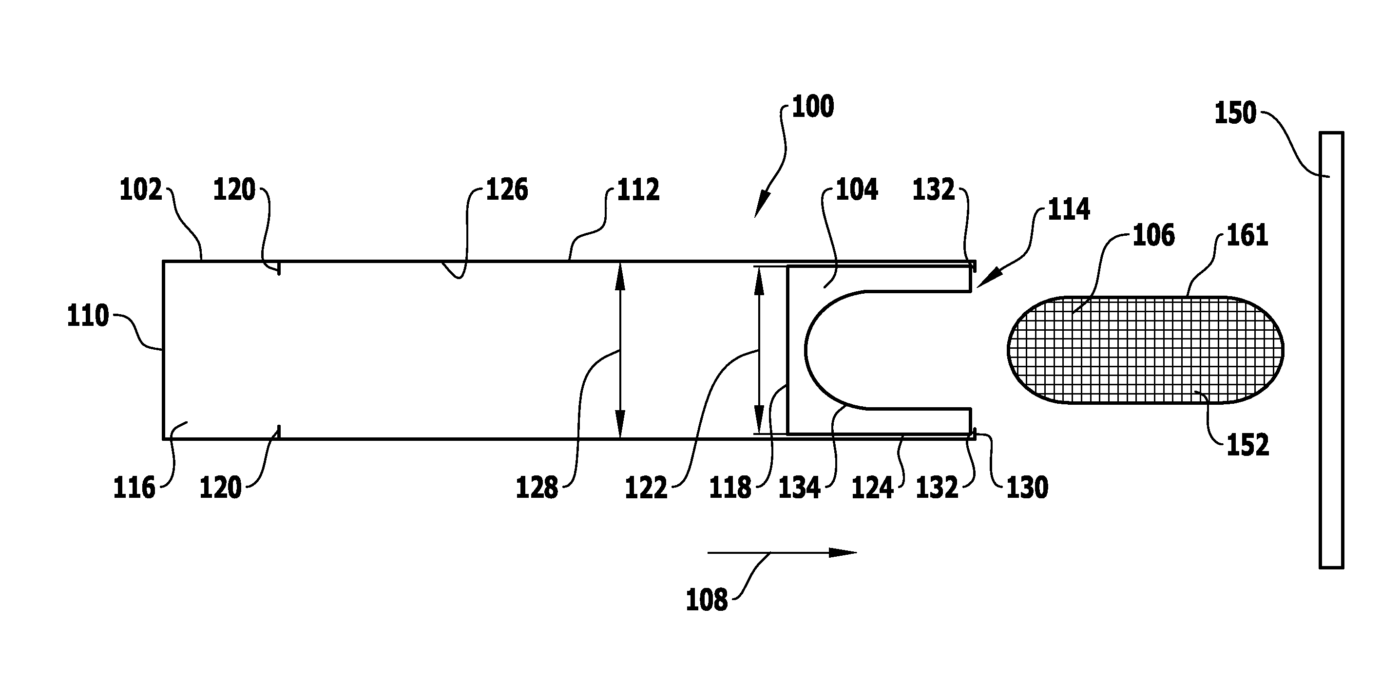
[0092]the projectile 106 shown in FIG. 7 comprises, in particular, for stabilization of the projectile 106 in the flight phase a stabilizing device 152.
[0093]The deformations of the projectile 106 caused by the air resistance can be reduced, in particular, avoided altogether by means of the stabilizing device 152.
[0094]The stabilizing device 152 is formed by square honeycombs and extends in both the radial and the axial direction over the entire extent of the projectile 106.
[0095]To produce the projectile 106, the stabilizing device 152 is placed in a mold into which, for example, a mixture of gelatin and water is subsequently introduced.
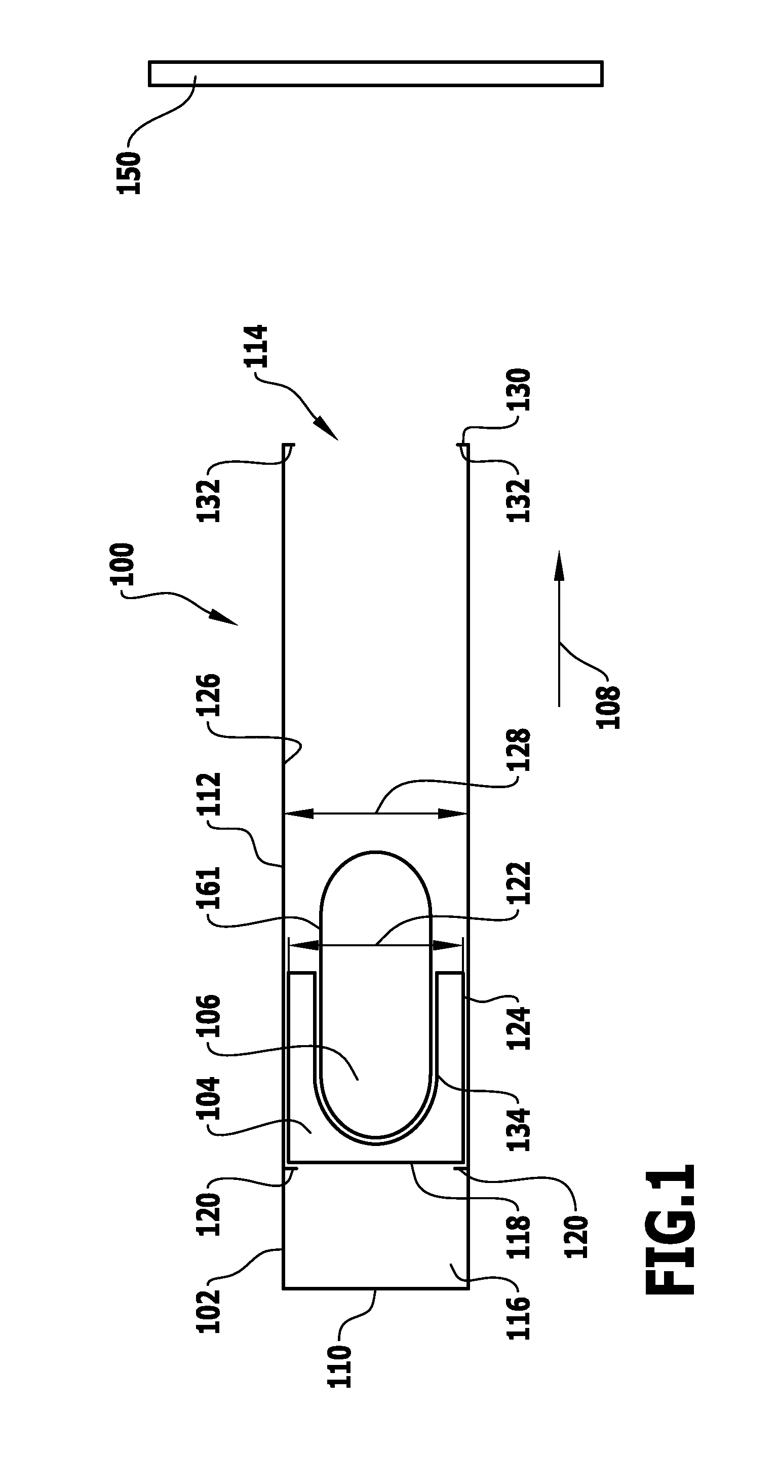
[0096]Apart from that, the embodiment of the gas gun 100 shown in FIG. 7 with the sabot 104 and the projectile 106 corresponds with respect to construction and operation to the embodiment of the gas gun 100 shown in FIGS. 1 and 3 to 6 with the sabot 104 and the projectile 106, to the above description of which reference is made in this respect.
third embodiment
[0097]the projectile 106 shown in FIG. 8 differs from the embodiment shown in FIG. 7 in that instead of a square honeycomb pattern, the stabilizing device 152 has a triangular honeycomb pattern.
[0098]Apart from that, the third embodiment of the projectile 106 shown in FIG. 8 corresponds with respect to construction and operation to the second embodiment shown in FIG. 7, to the above description of which reference is made in this respect.
[0099]In an embodiment (not shown) of the projectile 106 corresponding substantially to the third embodiment shown in FIG. 8, the honeycomb pattern is a hexagonal honeycomb pattern.
[0100]A fourth embodiment of the projectile 106 shown in FIG. 9 differs from the second embodiment shown in FIG. 7 in that the stabilizing device 152 comprises a cubic lattice formed by stabilizing elements 156.
[0101]The stabilizing elements 156 are connected to one another by connecting elements 158.
[0102]Lamellae 160 which are, for example, rectangular, are provided on t...
eighth embodiment
[0118]One, or a combination of several, of the stabilizing devices 152 shown in FIGS. 7 to 12 may be provided in the projectile 106.
[0119]Apart from that, the eighth embodiment of the projectile 106 shown in FIG. 13 corresponds with respect to construction and operation to the first embodiment shown in FIGS. 1 to 6, to the above description of which reference is made in this respect.
[0120]A ninth embodiment of the projectile 106 shown in FIG. 14 differs from the first embodiment shown in FIGS. 1 to 6 in that the shape of the projectile 106 is an ellipsoid.
[0121]A length 164 of the first semiaxis of the ellipsoid in this embodiment is, for example, approximately half of a length 166 of the second semiaxis of the ellipsoid.
[0122]The length of the third semiaxis is identical to the length of the first semiaxis, so that the projectile 106 has the shape of an ellipsoid of revolution.
PUM
 Abstract
Description
Claims
Application Information