Plug device with a changeable adapter
a technology of adapter and plug device, which is applied in the direction of coupling device connection, two-part coupling device, electrical apparatus, etc., can solve the problems of troublesome preparation of different transformers or battery chargers for different countries
- Summary
- Abstract
- Description
- Claims
- Application Information
AI Technical Summary
Problems solved by technology
Method used
Image
Examples
first embodiment
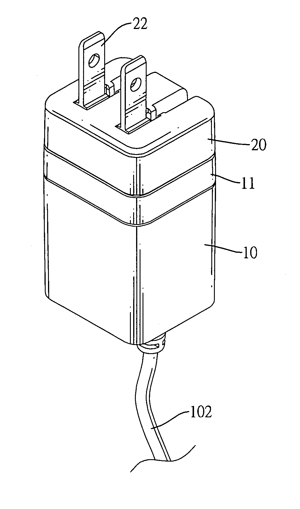
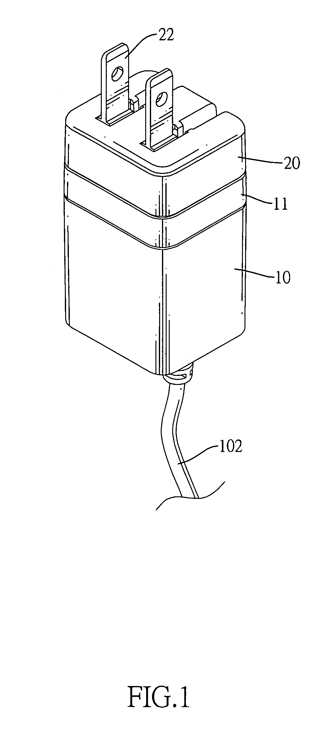
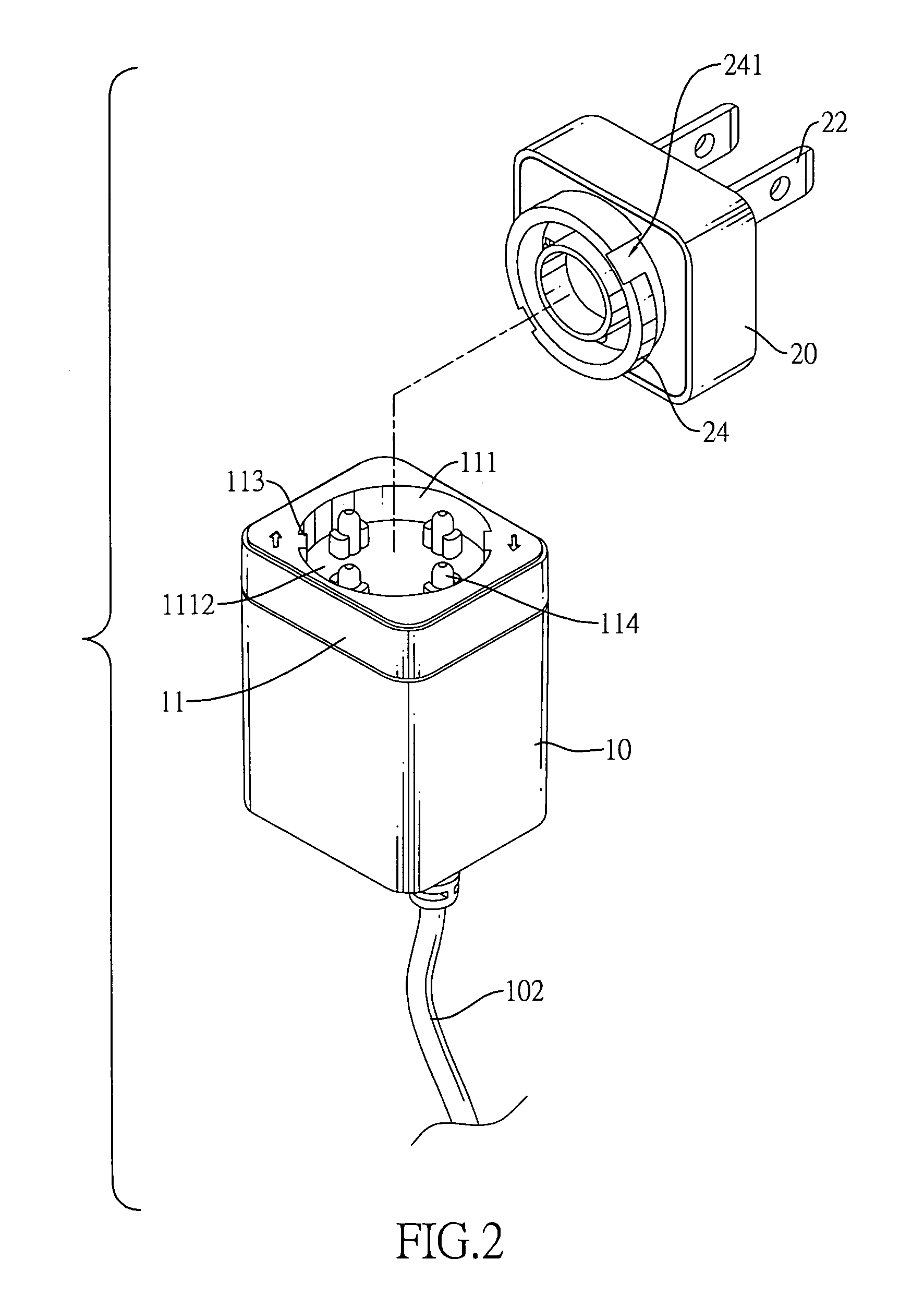
[0040]With reference to FIGS. 4 to 7, the adapter 20 is for use in the USA, Japan and China. The mounting panel 21 of the housing of the adapter 20 is substantially rectangular and has two mounting holes 211. Correspondingly, the outer cover 23 of the housing of the adapter 20 is substantially rectangular. The adapter 20 has two conductive sheets 212 and two prongs 22 and further has a prong mount 213 and a connecting rod 221. The conductive sheets 212 respectively correspond to the mounting holes 211 of the mounting panel 21. The prongs 22 are flat, parallel to each other and non-coplanar. The prong mount 213 is mounted on the mounting panel 21 and is disposed between the mounting holes 211 of the mounting panel 21. The connecting rod 221 is mounted on the prong mount 213 and has two ends respectively connected to the prongs 22.
second embodiment
[0041]With reference to FIGS. 8 to 11, the adapter 30 is for use in Australia. The mounting panel 31 of the housing of the adapter 30 has two mounting holes 311. The outer cover 33 of the housing of the adapter 30 has two prong holes 331 formed through the outer cover 33. The adapter 30 has two conductive sheets 312 and two prongs 32. The conductive sheets 312 respectively correspond to the mounting holes 311 of the mounting panel 31. The prongs 32 are flat, are respectively mounted through the prong holes 331 of the outer cover 33, are respectively connected to the conductive sheets 312 and are disposed unparallel to each other and in an upside down V-shaped form.
third embodiment
[0042]With reference to FIGS. 12 to 15, the adapter 40 is for use in continental Europe and most of the Middle East countries. The mounting panel 41 of the housing of the adapter 40 has two mounting holes 411. The outer cover 43 of the housing of the adapter 40 has two prong holes 431 and a fastening hole 432. The prong holes 431 are separately formed through the outer cover 43. The fastening hole 432 is formed in an inner surface of the outer cover 43 and is disposed between the prong holes 431. The adapter 40 has two conductive sheets 412 and two prongs 42 and further has a prong mount 421 and a fastener 423. The conductive sheets 412 respectively correspond to the mounting holes 411 of the mounting panel 41. The prong mount 421 is mounted in the housing of the adapter 40, is disposed between the mounting holes 411 of the mounting panel 41 and has a countersink 422 formed through the prong mount 421 and corresponding to the fastening hole 432 of the outer cover 43. The prongs 42 a...
PUM
 Abstract
Description
Claims
Application Information
 - R&D
- Intellectual Property
- Life Sciences
- Materials
- Tech Scout
- Unparalleled Data Quality
- Higher Quality Content
- 60% Fewer Hallucinations
Browse by: Latest US Patents, China's latest patents, Technical Efficacy Thesaurus, Application Domain, Technology Topic, Popular Technical Reports.
© 2025 PatSnap. All rights reserved.Legal|Privacy policy|Modern Slavery Act Transparency Statement|Sitemap|About US| Contact US: help@patsnap.com


