
Impact indicator

a technology of impact indicators and indicators, applied in the direction of instruments, force/torque/work measurement apparatus, acceleration measurement using interia forces, etc., can solve problems such as objects that are susceptible to damag

Active Publication Date: 2012-08-07
SHOCKWATCH
View PDF31 Cites 39 Cited by
  • Summary
  • Abstract
  • Description
  • Claims
  • Application Information

AI Technical Summary

Benefits of technology

[0003]According to another embodiment of the present disclosure, an impact indicator includes a housing; a mass member located within the housing where the housing comprises a plurality of sidewalls forming a translation path for movement of the mass member within the housing; and at least one spring member having ends located in respective seat positions on the sidewalls, and w...

Problems solved by technology

For example, some types of objects may be susceptible to damage if dropped or a significant impact is received.

Method used


Image

  • Impact indicator
  • Impact indicator
  • Impact indicator

Examples


Embodiment Construction

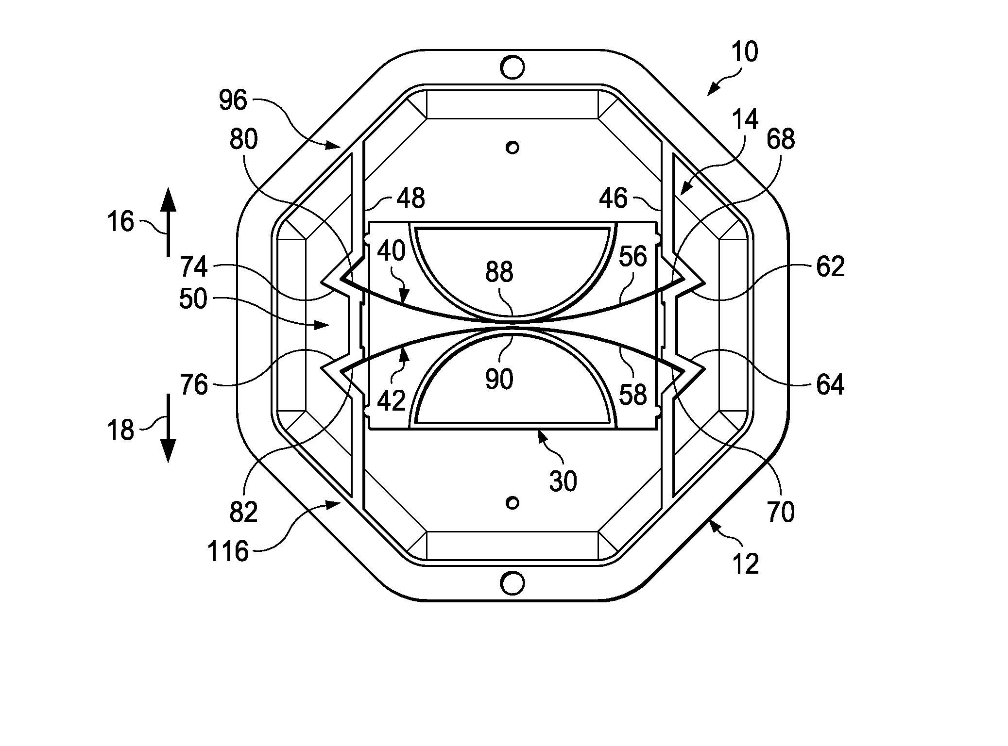
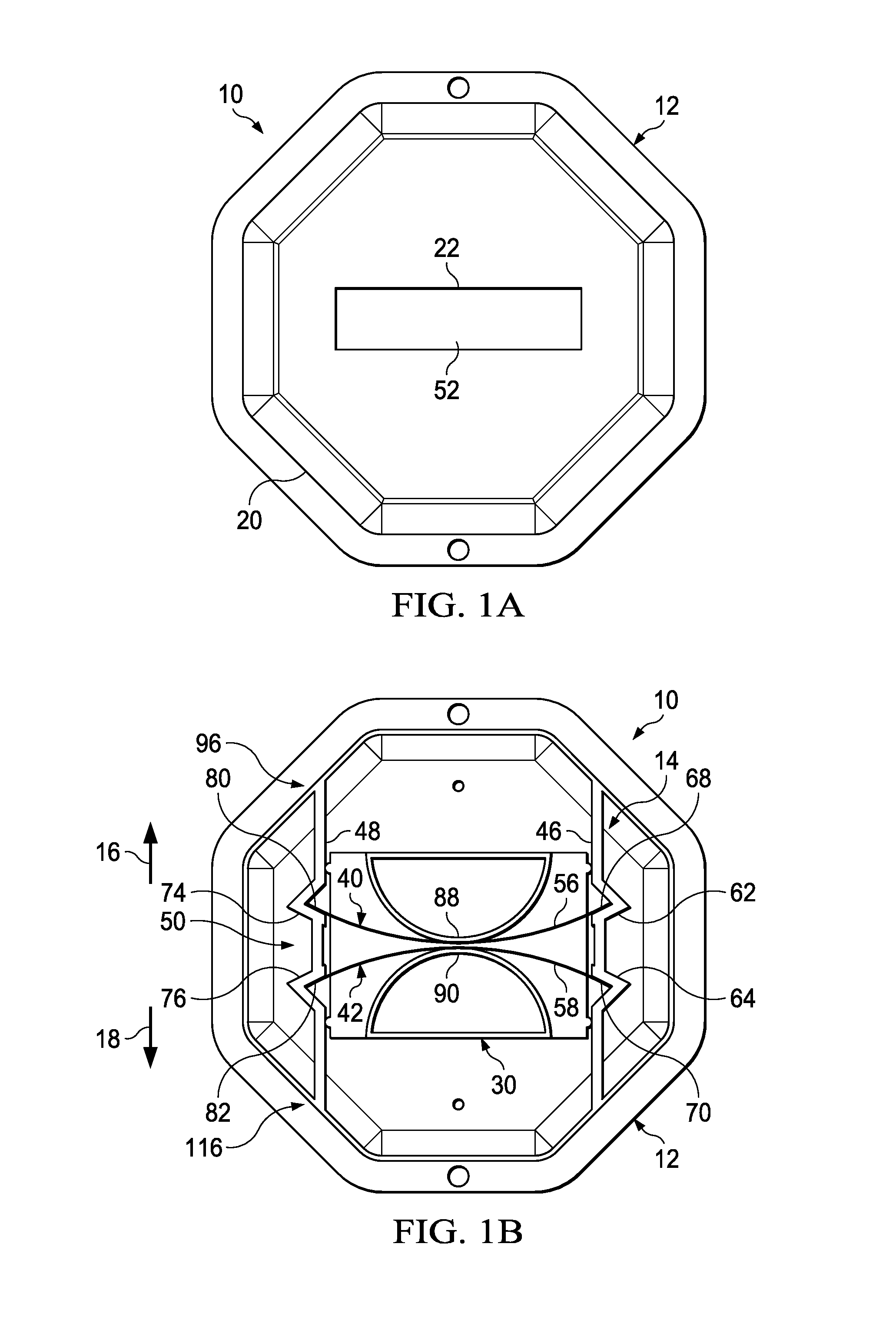
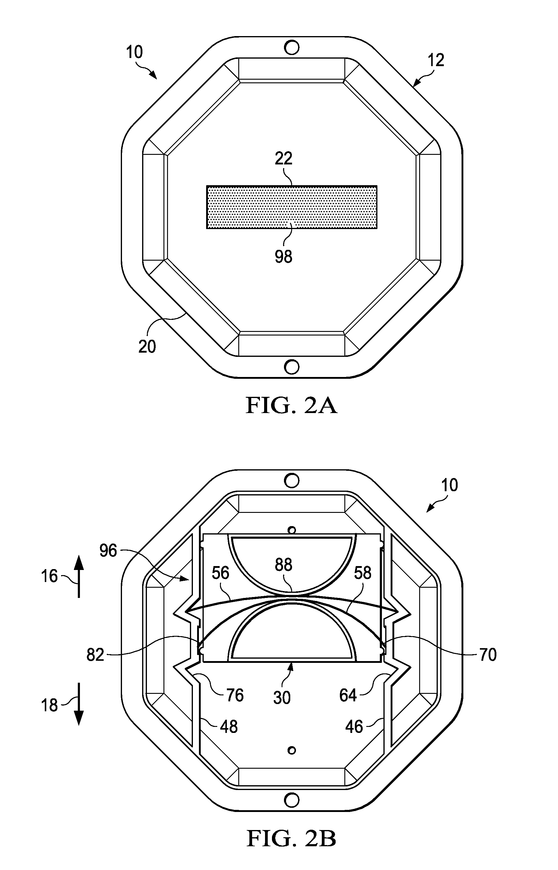
[0022]Embodiments of the present disclosure provide a device and technique for impact detection and indication. According to one embodiment, an impact indicator includes a housing; a mass member located within the housing where the housing is configured to enable movement of the mass member from a first position to a second position within the housing in response to receipt by the housing of an acceleration event; and first and second spring members disposed within the housing and configured to bias the mass member to the first position. In response to receipt by the housing of the acceleration event, the mass member is configured to overcome the biasing force of the first spring member and move from the first position to the second position, and wherein each of the first and second spring members extends across a medial portion of the mass member. Embodiments of the present disclosure enable impact and / or acceleration event detection while preventing or substantially preventing a r...


PUM


Abstract

According to one aspect of the present disclosure, a device and technique for impact detection and indication is disclosed. The device includes a housing; a mass member located within the housing, the housing configured to enable movement of the mass member from a first position to a second position within the housing in response to receipt by the housing of an acceleration event; and first and second spring members disposed within the housing and configured to bias the mass member to the first position, wherein, in response to receipt by the housing of the acceleration event, the mass member is configured to overcome the biasing force of the first spring member and move from the first position to the second position, and wherein each of the first and second spring members extends across a medial portion of the mass member.

Description

BACKGROUND[0001]During manufacturing, storage or transit, many types of objects need to be monitored due to the sensitivity or fragility of the objects. For example, some types of objects may be susceptible to damage if dropped or a significant impact is received. Thus, for quality control purposes and / or the general monitoring of transportation conditions, it is desirable to determine and / or verify the environmental conditions to which the object has been exposed.BRIEF SUMMARY[0002]According to one aspect of the present disclosure, a device and technique for impact detection is disclosed. The impact indicator includes a housing; a mass member located within the housing where the housing is configured to enable movement of the mass member from a first position to a second position within the housing in response to receipt by the housing of an acceleration event; and first and second spring members disposed within the housing and configured to bias the mass member to the first positi...

Claims


Application Information

Patent Timeline
IPC IPC(8): G01P15/02
CPCG01L5/0052H01H35/14G01P15/036H01H9/16G01P15/04G01P15/03G01P15/02G01P15/00G01L23/00G01L5/00G01N3/30
Inventor BRANCH, CLINTON A.
Owner SHOCKWATCH
Learn More