Remote control device

a remote control and control device technology, applied in the field of remote control devices, can solve the problems of inefficiency and cost of two people, and achieve the effect of reducing the cost of using two peopl

Active Publication Date: 2012-08-07
FUJIFILM SONOSITE
View PDF7 Cites 34 Cited by
  • Summary
  • Abstract
  • Description
  • Claims
  • Application Information

AI Technical Summary

Problems solved by technology

Using two people is costly and inefficient.

Method used


Image

  • Remote control device
  • Remote control device
  • Remote control device

Examples


Embodiment Construction

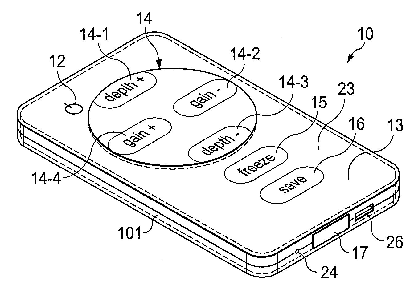
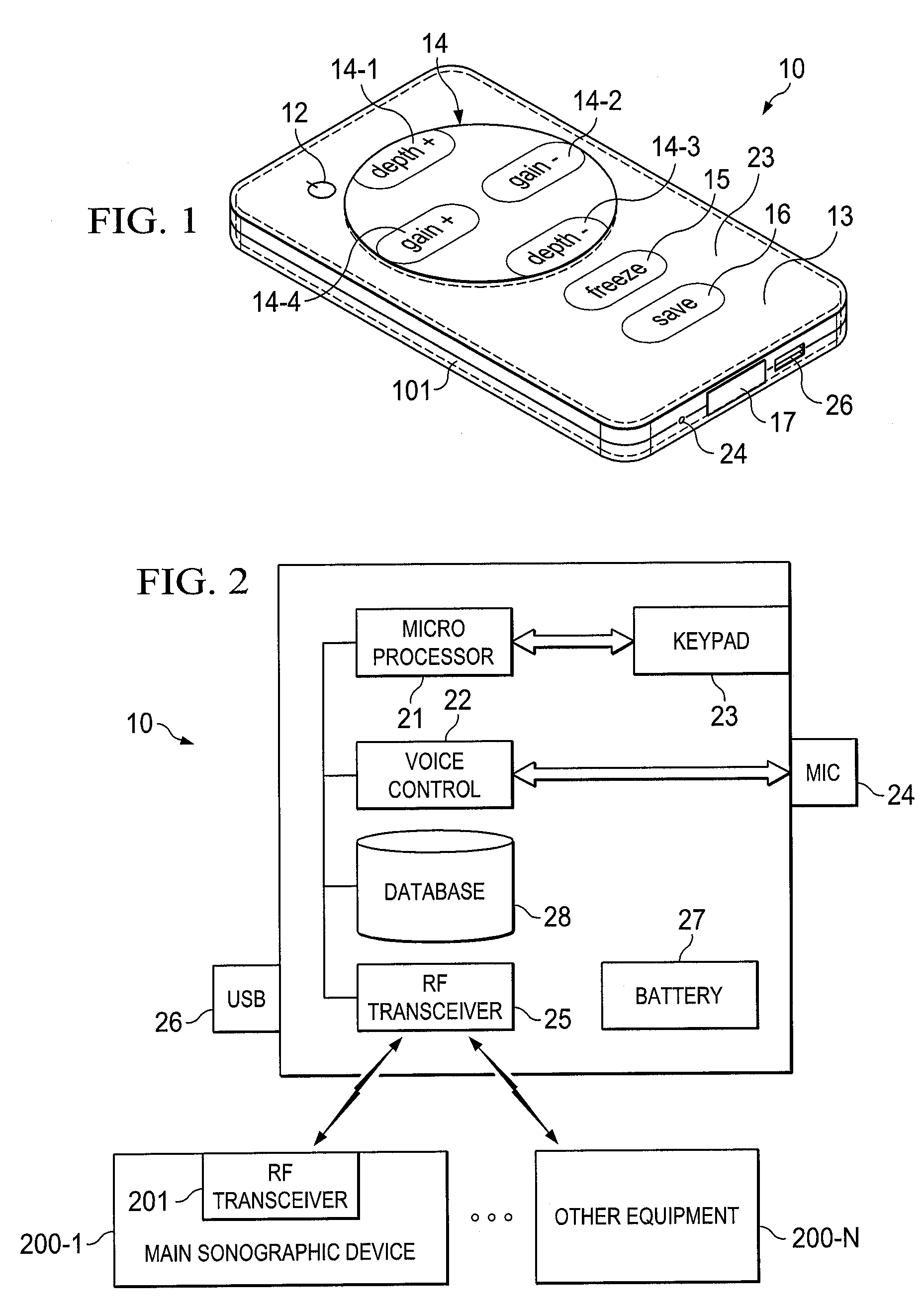
[0013]FIG. 1 illustrates one embodiment of a remote control device, such as device 10, in accordance with an aspect of the invention. Device 10 contains shell 101 and key pad 23. The key pad wraps around the internal circuit board (not shown) and seals against the shell. The key pad acts as a seal to the unit and also encloses the battery case. This provides a very clean back and side surface without screw holes to trap grunge and germs. The battery, in this embodiment, is charged inductively.

[0014]In one embodiment, key pad 23 is a single piece of silicon ballistae having an anti-microbial surface that is easily cleanable. Key pad 23 stretches over the entire top surface of the remote device making it easier to clean. In one embodiment, the silicon is stretched over two-part shell 101 and tucked in between the two parts of the shell prior to the top half of the shell being bonded to the bottom half.

[0015]Dimensions of device are, in one embodiment, about 2½ inches by 4 inches by 0....


PUM


Abstract

The present invention is directed to a system and method which allows a device user who is within a sterile environment to interact remotely with a device physically located outside of the sterile zone. In one embodiment, the remote link is wireless and allows the operator to adjust critical controls without breaking the sterile environment. The remote device is designed to be sheathed in sterile sheaths and further designed, in one embodiment, to keep the remote control element from physically interacting with the patient and in some cases with the device operator. In one embodiment, the remote device operator interacts with the remote device verbally.

Description

BACKGROUND OF THE INVENTION[0001]There are many situations were medical equipment, such as sonogram devices, must be used in a sterile environment. When such equipment is used in a sterile environment the person using the equipment (a sonographer in the case of sonographic devices) must from time to time interact with the device controls for a variety of reasons. However, because of the sterile conditions the sonographer must have a method of interaction with the equipment that will not compromise the sterile environment.[0002]Some areas of particular concern occurs when sonography is used for assisting with nerve blocks and peripherally inserted central catheter (PICC) lines both of which procedures must be performed in sterile environments. Thus, the patient is sterile, the doctor and nurses are sterile, but the sonograph machine is sitting a way from the sterile zone and is not sterile. If the operator were to touch the machine, as would occur in order to manually adjust a dial o...

Claims


Application Information

Patent Timeline
Patent Type & Authority Patents(United States)
IPC IPC(8): G08C19/22
CPCA61B8/00A61B8/467A61B8/582
Inventor DUNBAR, LEEREISENBICHLER, MICHAELLOCKHART, SCOTT N.
Owner FUJIFILM SONOSITE
Why Eureka
Try Eureka