Circuit breaker compartment arc flash venting system

a circuit breaker and compartment technology, applied in switchgear arrangements, non-enclosed substations, substations, etc., can solve problems such as internal arcing faults, severe mechanical and thermal stress, and operator injuries, and achieve safe and secure channeling

Active Publication Date: 2012-08-14
SIEMENS IND INC
View PDF7 Cites 36 Cited by
  • Summary
  • Abstract
  • Description
  • Claims
  • Application Information

AI Technical Summary

Benefits of technology

[0018]Another purpose of this invention is to provide a channel within a switchgear apparatus for safely and securely channeling of sudden gaseous and particulate discharge occurring from an arcing fault inside the switchgear.
[0019]Yet another purpose of this invention is to provide an insulative venting means for a switchgear apparatus which allows for the safe and secure channeling of a sudden gaseous and particulate discharge occurring from an arcing fault inside the switchgear.

Problems solved by technology

This sudden discharge of gaseous and particulate material normally damages the switchgear enclosure and its contents, but may also cause severe injury to an operator who may happen to be nearby.
An internal arcing fault can be caused by insulation degradation, insulation, contamination, entrance of vermin, foreign objects coming into contact with the energized bus, or any other unplanned condition that creates an electrical discharge path through air.
The expanding plasma creates severe mechanical and thermal stress in the equipment which can blow open doors and covers and burn through or fragment the enclosure and / or cause severe injury to an operator who may happen to be nearby.

Method used


Image

  • Circuit breaker compartment arc flash venting system
  • Circuit breaker compartment arc flash venting system
  • Circuit breaker compartment arc flash venting system

Examples


Embodiment Construction

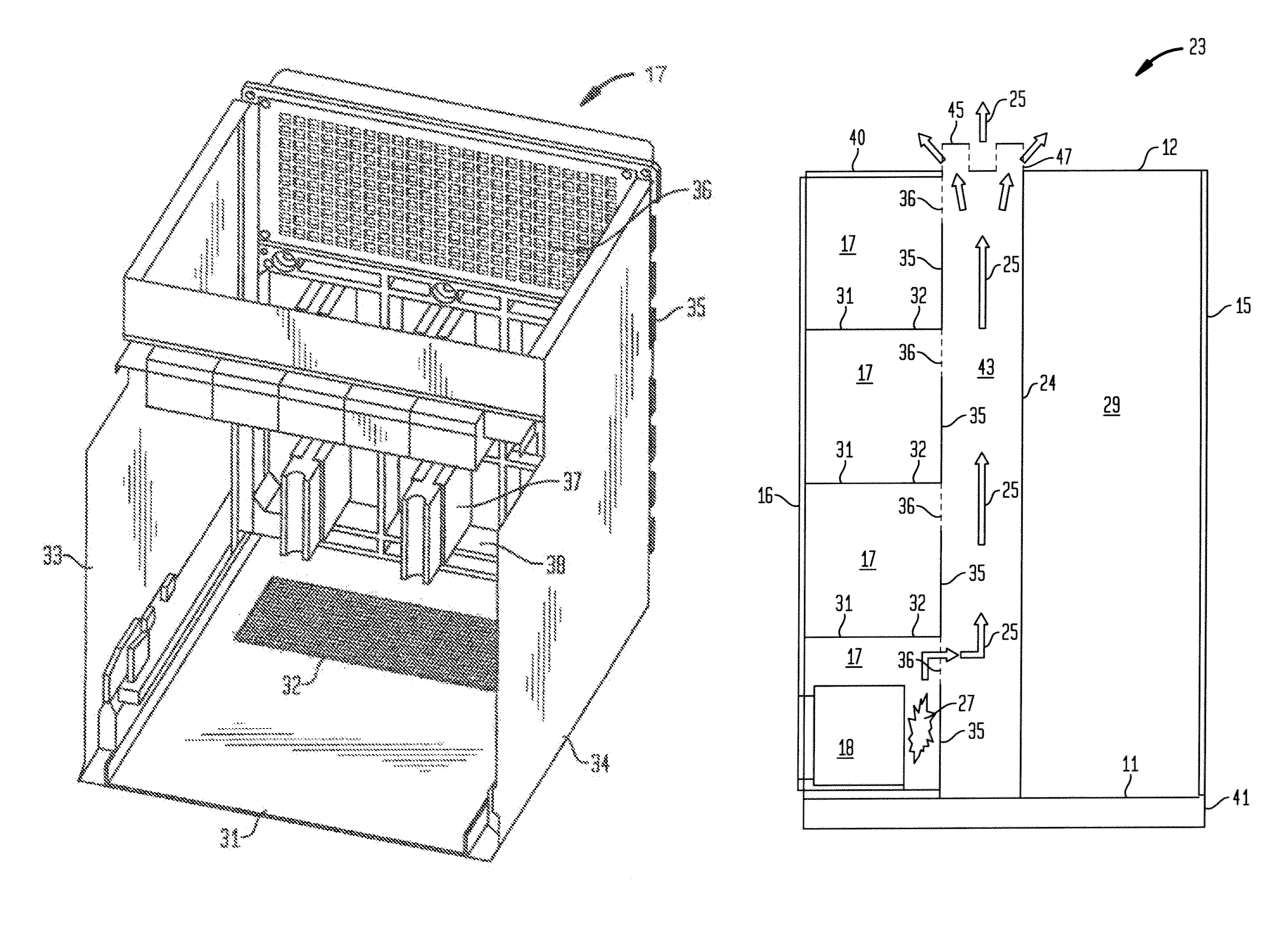
[0030]This invention provides a method and apparatus for an improved switchgear apparatus. This invention provides a means to vent hot gasses from the circuit breaker compartments in the front of the switchgear through the section bus compartment to the top of the switchgear.

[0031]This invention further uses an insulated section bus compartment with three individual chambers, one for each phase, to reduce the possibility of having an arc re-strike in the bus compartment.

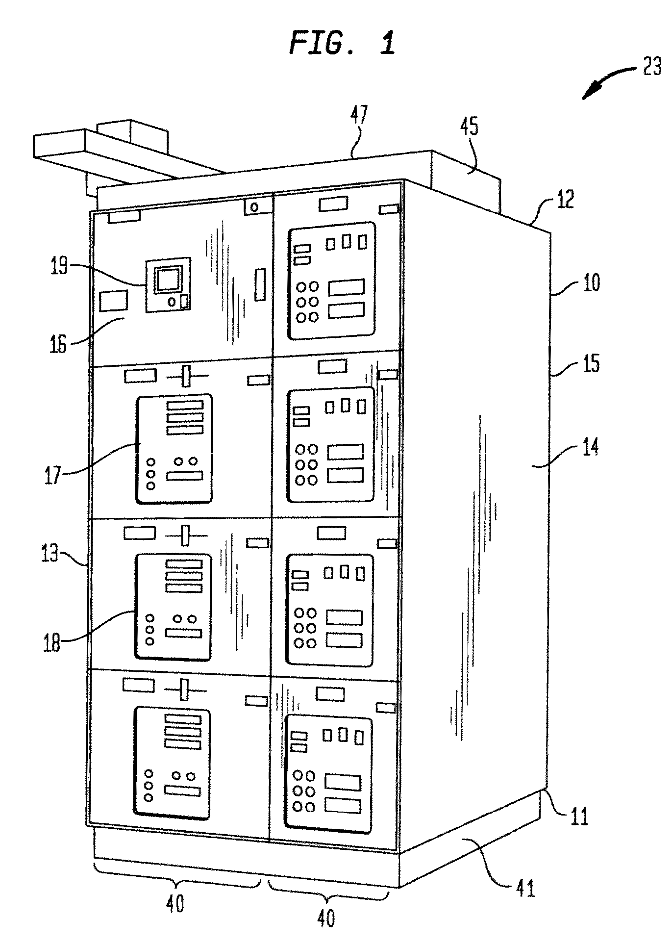
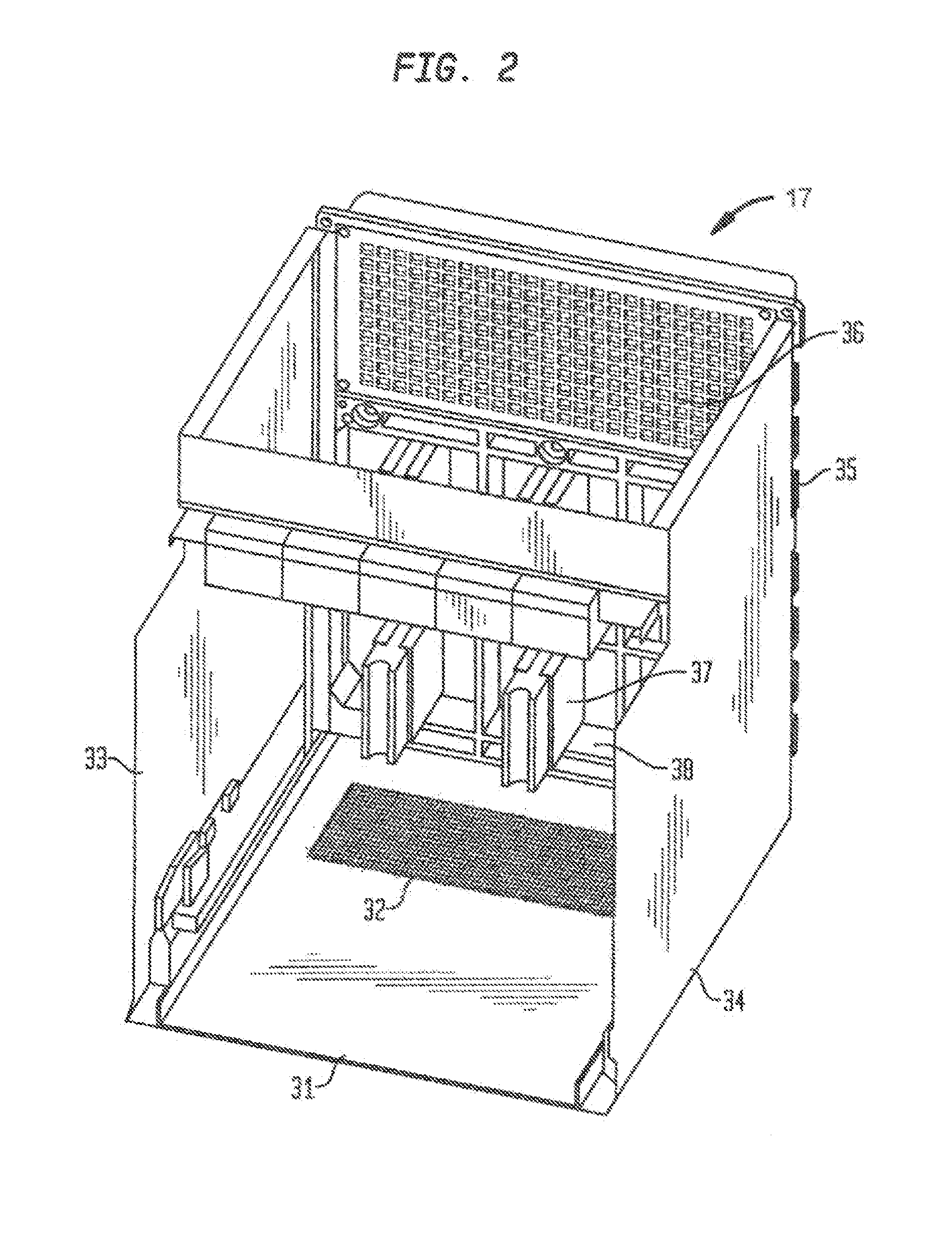
[0032]FIG. 1 is a novel switchgear assembly 23, which is used to illustrate an embodiment of the present invention. As shown in FIG. 1, the switchgear assembly 23, comprises of a plurality of switchgear sections 40, assembled on at least one mounting base or sill channel 41. Each switchgear section 40, can contain up to six compartments 17, such as, a circuit breaker compartment 17, containing one circuit breaker 18, per each circuit breaker compartment 17. The switchgear assembly 23, further comprises of an enclosur...


PUM


Abstract

The present invention relates generally to a switchgear apparatus. More particularly, the invention encompasses a circuit breaker compartment arc flash venting system for a switchgear apparatus. The present invention also relates to enclosures for switchgear, panel boards, circuit breakers, and more particularly to an enclosure for low voltage switchgear and switchboard assemblies. The enclosure can be a walk-in type enclosure or a non-walk-in type enclosure. This invention further provides a method and apparatus for channeling plasma (hot arc gasses) that are generated from an arc. The circuit breaker compartment arc flash venting system is an integral part of an arc resistant switchgear assembly. The arc flash venting system works in conjunction with the bus insulation and ventilation systems in the switchgear apparatus to channel hot arc gasses (plasma) from a breaker compartment in the event of an internal arcing fault in the breaker compartment. The gasses are channeled to exit the upper rear of the breaker compartment and into the insulated section bus compartment. The hot arc gasses and other particulates then travel upward through the section bus compartment where they are routed to and safely discharged from the vent structure on the roof of the switchgear apparatus.

Description

CROSS-REFERENCE TO RELATED APPLICATION[0001]The instant patent application claims priority to and the benefit of the filing date of U.S. Provisional Patent Application Ser. No. 61 / 030,321, filed on Feb. 21, 2008, titled “Circuit Breaker Compartment Arc Flash Venting System,” the entire disclosure of which is incorporated herein by reference.FIELD OF THE INVENTION[0002]The present invention relates generally to a switchgear apparatus. More particularly, the invention encompasses a circuit breaker compartment arc flash venting system for a switchgear apparatus. The present invention also relates to enclosures for switchgear, panel boards, circuit breakers, and more particularly to an enclosure for low voltage switchgear and switchboard assemblies. The enclosure can be a walk-in type enclosure or a non-walk-in type enclosure. This invention further provides a method and apparatus for channeling plasma (hot arc gasses) that are generated from an arc. The circuit breaker compartment arc ...

Claims


Application Information

Patent Timeline
Patent Type & Authority Patents(United States)
IPC IPC(8): H01H9/02
CPCH02B13/025H01H9/342H02B1/56
Inventor JOSTEN, HARRY W.FLOWERS, KEITHRAJVANSHI, RAHUL
Owner SIEMENS IND INC
Why Eureka
Try Eureka