Intake structure of vehicle

a technology for vehicle intake and intake, which is applied in the direction of vehicle components, propulsion parts, and gas exhaust of propulsion units, etc., can solve the problem of difficulty in disposing of air cleaners having the required capacity secured

Inactive Publication Date: 2012-08-28
HONDA MOTOR CO LTD
View PDF7 Cites 13 Cited by
  • Summary
  • Abstract
  • Description
  • Claims
  • Application Information

AI Technical Summary

Problems solved by technology

However, if the vehicle body is reduced in size, the position to dispose an air cleaner is limited, thus leading to a problem that it is difficult to dispose an air cleaner having a required capacity secured.

Method used


Image

  • Intake structure of vehicle
  • Intake structure of vehicle
  • Intake structure of vehicle

Examples


first embodiment

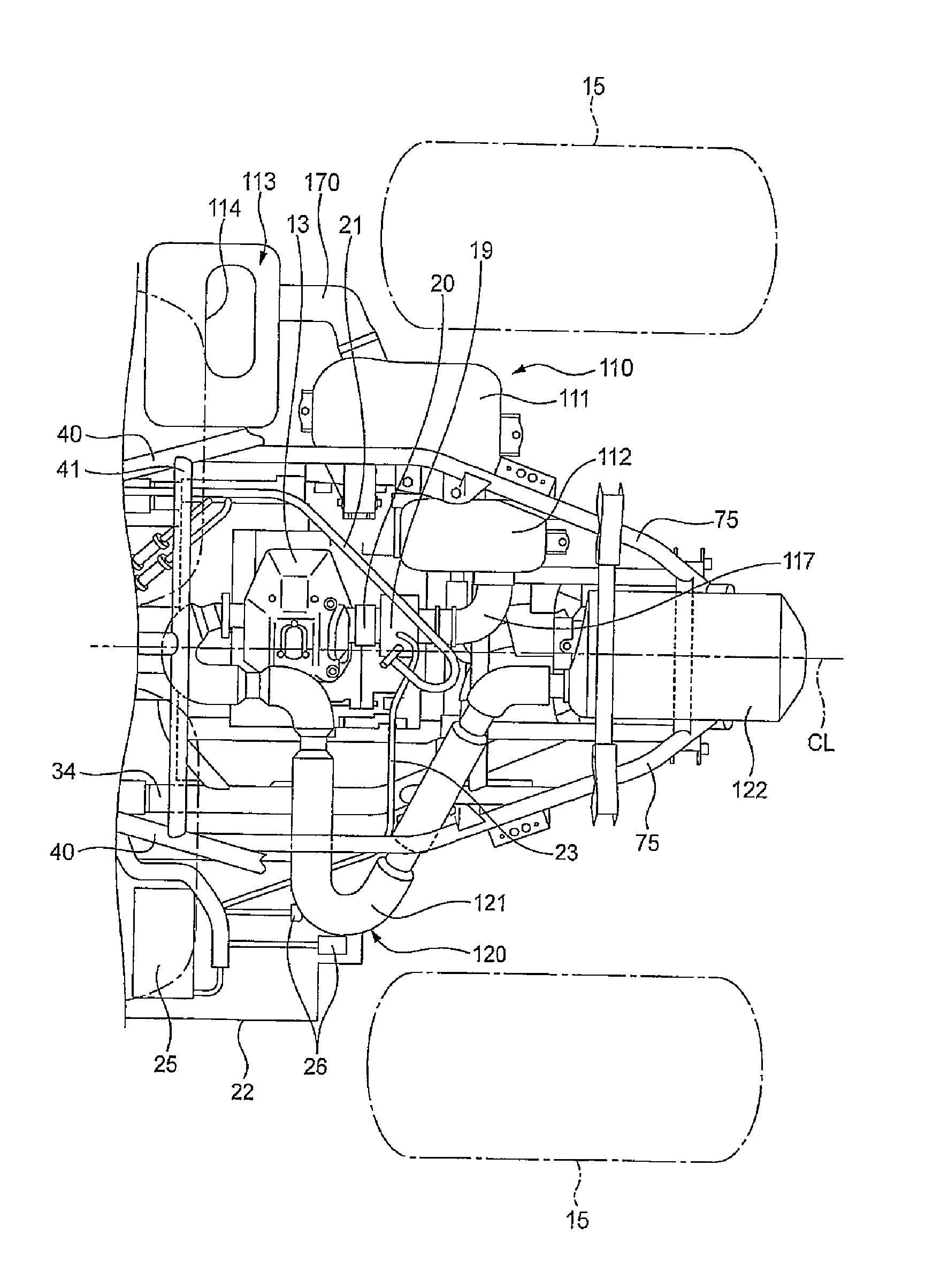
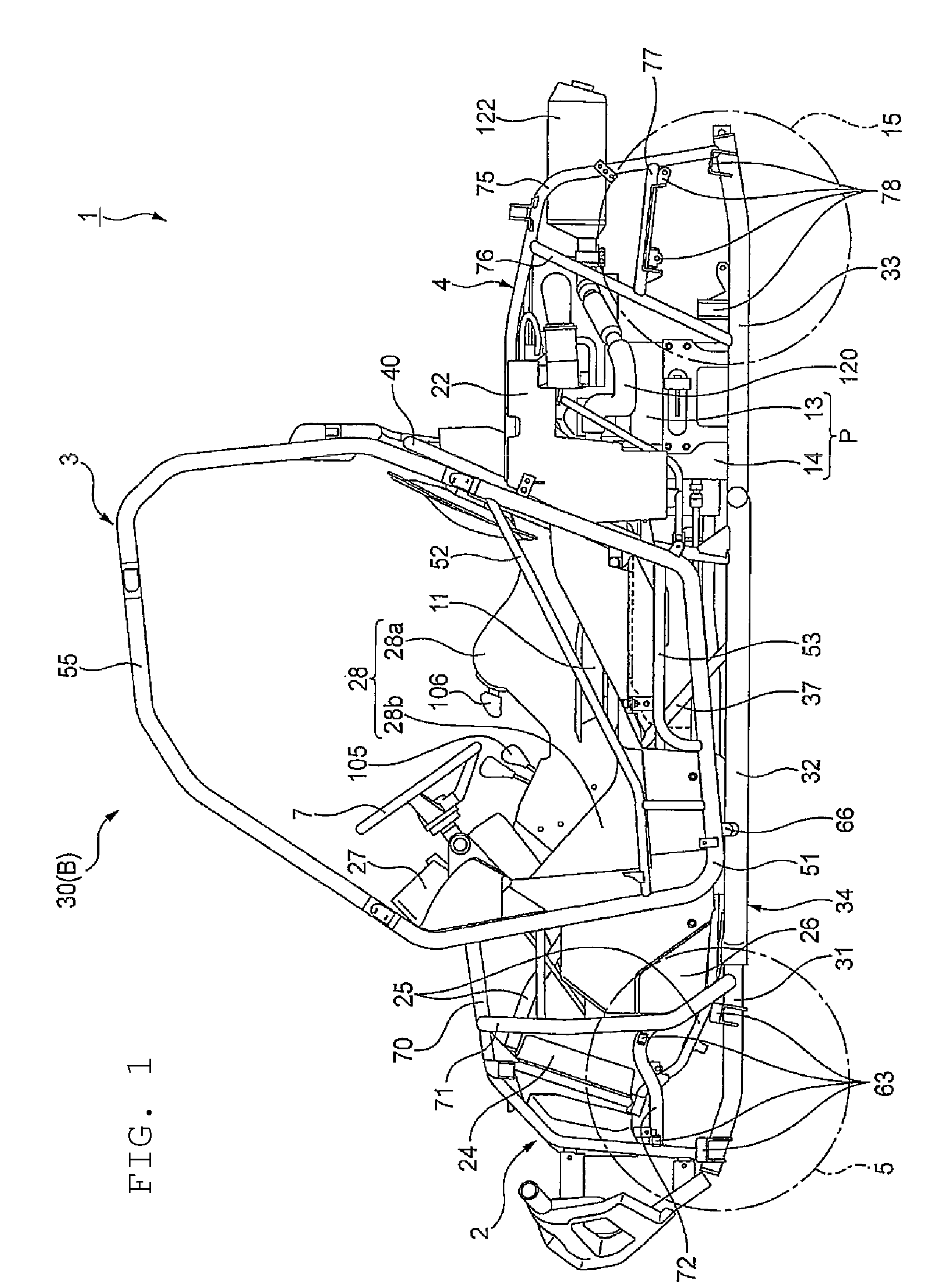
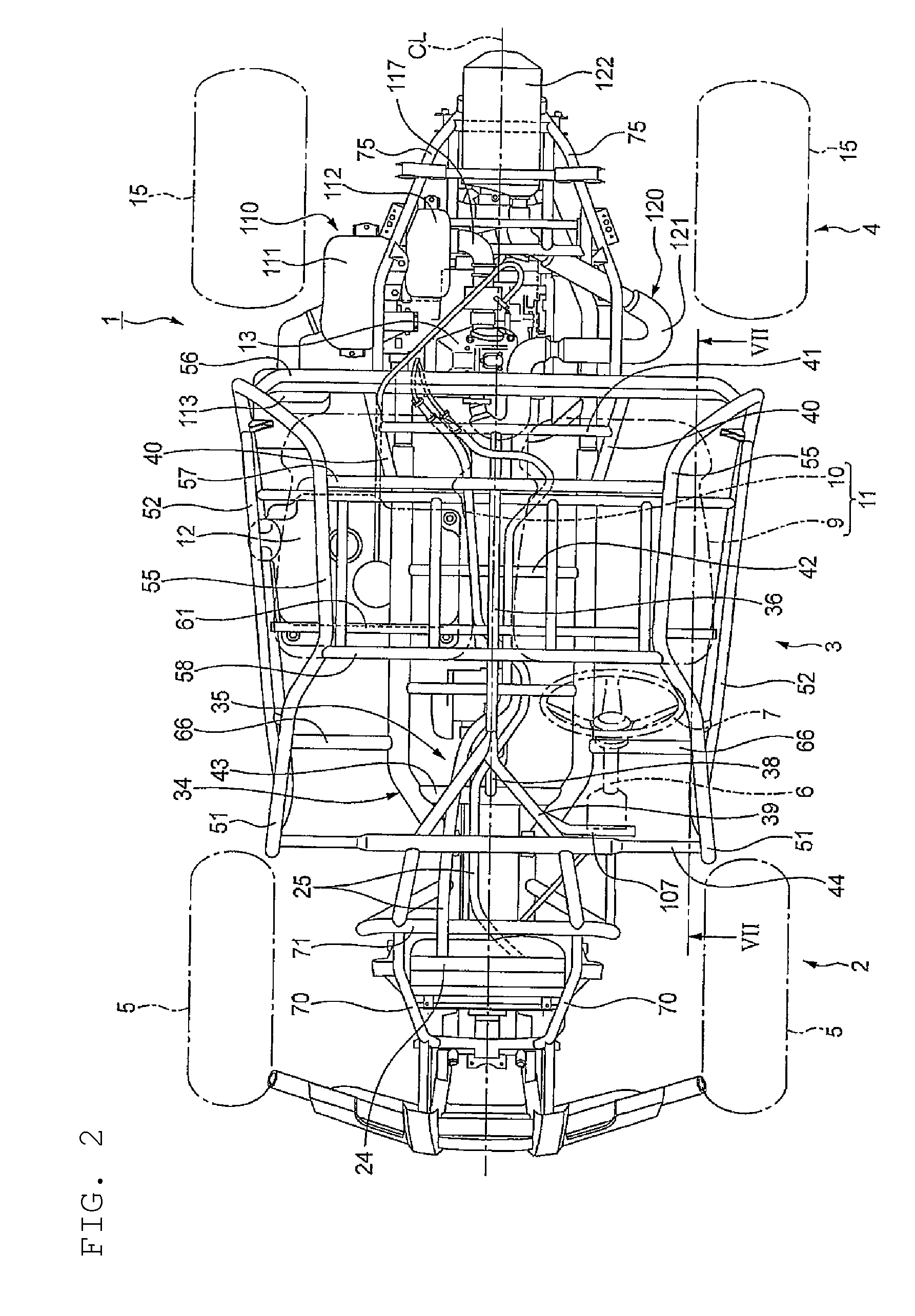
[0075]the present invention provides an intake structure of a vehicle including: a vehicle body frame; a pair of occupant seats being arranged side by side in a vehicle width direction in the vehicle body frame, and constituting a driver's seat and a passenger seat; an internal combustion engine for generating a driving force; and an air cleaner for purifying air and supplying the purified air to the internal combustion engine. Moreover, the air cleaner includes a first air cleaner chamber and a second air cleaner chamber that are disposed to sandwich a part of the vehicle body frame.

second embodiment

[0076]the present invention provides the following characteristic in addition to the configuration of the first aspect. Specifically, the intake structure of a vehicle further includes: a pair of lower frames constituting the vehicle body frame, and being disposed respectively in left and right lower portions of the vehicle body so as to extend in a front-rear direction; a pair of left and right rear upper frames extending upward respectively from rear ends of the lower frames, thereafter, being bent in such a manner as to cover the internal combustion engine, and then extending frontward; and a pair of rear upright frames coupling the respective rear upper frames to the corresponding lower frames. In addition, the internal combustion engine is disposed behind the occupant seats and supported substantially on a center line of a vehicle body in the rear frame portion. Moreover, the air cleaner is disposed behind any one of the driver's seat and the passenger seat and on a side of the...

third embodiment

[0077]the present invention provides the following characteristic in addition to the configuration of the first aspect. Specifically, the intake structure of a vehicle further includes: an air cleaner element for removing dust in air, the air cleaner element being disposed inside the first air cleaner chamber; a coupling tube allowing the first air cleaner chamber and the second air cleaner chamber to communicate with each other therethrough; and a connecting tube allowing the second air cleaner chamber and the internal combustion engine to communicate with each other therethrough so as to supply the purified air to the internal combustion engine. In addition, the first air cleaner chamber is disposed outward of any one of the corresponding lower frame, the corresponding rear upper frame, and the corresponding rear upright frame, in the vehicle width direction, while the second air cleaner chamber is disposed inward of the one of the corresponding lower frame, the corresponding rear...


PUM


Abstract

An intake structure for a vehicle includes a vehicle body frame, a pair of occupant seats, an internal combustion engine, and an air cleaner. The pair of occupant seats are arranged side by side in a vehicle width direction in the vehicle body frame and includes a driver's seat and a passenger seat. The internal combustion engine is configured to generate a driving force. The air cleaner is configured to purify air and supply the purified air to the internal combustion engine. The air cleaner includes a first air cleaner chamber and a second air cleaner chamber that are disposed to sandwich a part of the vehicle body frame.

Description

CROSS-REFERENCE TO RELATED APPLICATIONS[0001]The present application claims priority under 35 U.S.C. §119 to Japanese Patent Application No. 2008-253174, filed Sep. 30, 2008. The contents of this application are incorporated herein by reference in their entirety.BACKGROUND OF THE INVENTION[0002]1. Field of the Invention[0003]The present invention relates to an intake structure for a vehicle.[0004]2. Discussion of the Background[0005]There has heretofore been known a vehicle structure in which an air cleaner is disposed in a rear frame portion (refer to, for example, Japanese Patent Application Publication No. 2006-103378). The vehicle frame structure of a vehicle described in Japanese Patent Application Publication No. 2006-103378 includes a front frame portion, a center frame portion, and the rear frame portion. In the vehicle frame structure, the air cleaner is disposed in a space surrounded by rear lower frames and side frames of the rear frame portion.[0006]It is required that s...

Claims


Application Information

Patent Timeline
Patent Type & Authority Patents(United States)
IPC IPC(8): B60K13/02
CPCB60K13/02B60Y2200/114
Inventor MIURA, TAKAYOSHI
Owner HONDA MOTOR CO LTD
Why Eureka
Try Eureka