Direct-flame fuel cell

a fuel cell and direct-flame technology, which is applied in the direction of fuel cells, solid electrolyte fuel cells, cell components, etc., can solve the problems of deteriorating the power generation performance of the cell to a large extent, and achieve the effect of suppressing the deterioration of the power generation performance of the cell and long li

Active Publication Date: 2012-08-28
SHINKO ELECTRIC IND CO LTD
View PDF16 Cites 0 Cited by
  • Summary
  • Abstract
  • Description
  • Claims
  • Application Information

AI Technical Summary

Benefits of technology

[0005]An object of the present invention is to provide a direct-flame fuel cell which suppresses deterioration of the power generation performance of a cell by lowering the degree of attachment of soot to the anode.
[0009]According to the invention, the attachment of soot to the anode is suppressed by the function of the one or more kinds of alkaline metal compounds or alkaline earth metal compounds, whereby the deterioration of the power generation performance of the cell can be suppressed. The invention can thus provide a direct-flame fuel cell having a long life.

Problems solved by technology

The soot that is attached to the anode is a cause of deteriorating the power generation performance of the cell to a large extent over time.

Method used


Image

  • Direct-flame fuel cell
  • Direct-flame fuel cell
  • Direct-flame fuel cell

Examples


example 1

[0039]A cell is produced according to the following procedure.

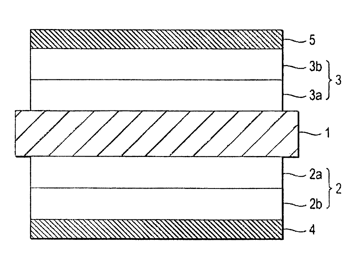
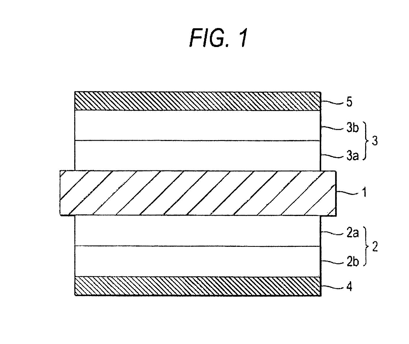
[0040]An SDC (samaria-doped ceria, Sm0.2Ge0.8O1.9) ceramic substrate to be used as a solid electrolyte is prepared. This SDC ceramic substrate which is a circular plate of 180 (μm in thickness and 15 mm in diameter is produced in the following manner. A green sheet is shaped by a doctor blade method. Fibrous cloths are applied to both surfaces of the green sheet and the green sheet is pressed at about 15 MPa (150 kg / cm2) by hydraulic pressing, whereby the surfaces of the green sheet is roughened. The thus-processed green sheet is punched into a circular plate and then fired at 1,300° C.

[0041]N0.9Co0.1Ox paste added with SDC at 60 wt % is printed on one surface (area: 1.8 cm2) of the ceramic substrate in an area of 1.3 cm2 as an inner anode layer, and Ni0.9Co0.1Ox paste added with CaCO3, Rh2O3 and SDC at 3 wt %, 5 wt % and 30 wt %, respectively, is printed thereon in an area of 1.3 cm2 as an outer anode layer. SSC (samariu...

example 2

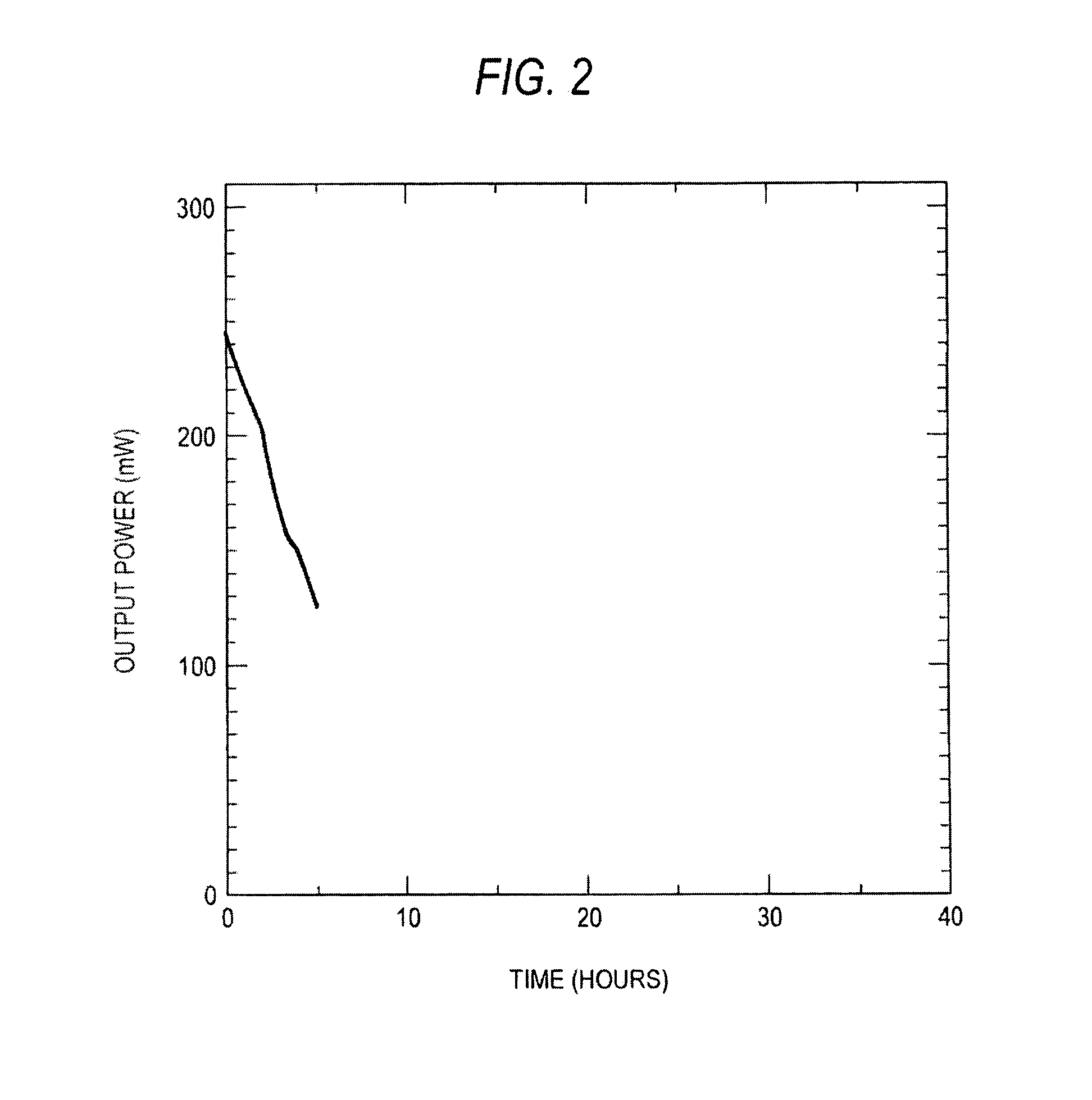
[0045]Experiments are conducted in the same manner as in Example 1 while the amount of CaCO3 added to the paste for the outer anode layer is varied, and the time taken until the output power of the fuel cell decreased to 50% of an initial value is measured. FIG. 6 shows results. It is seen from the results that the practical amount of CaCO3 added in the outer anode layer is about 1 to 10 wt %, preferably, 2 to 7 wt %.

[0046]As is understood from the above, the practical amount of a calcium compound that is added in the anode can be determined easily on the basis of the kinds of anode material and calcium compound used, flame conditions, etc. by conducting simple experiments. Likewise, the amount of a compound added other than calcium compounds that is effective in suppressing soot generation can be determined easily on the basis of the kinds of anode material and compound used, flame conditions, etc. by conducting simple experiments.


PUM

PropertyMeasurementUnit
thicknessaaaaaaaaaa
thicknessaaaaaaaaaa
areaaaaaaaaaaa

Abstract

A direct-flame fuel cell according to the invention has a cell in which a solid electrolyte 1 is sandwiched between an anode 2 and a cathode 3. The anode 2 contains one or more kinds of alkaline metal compounds or alkaline earth metal compounds which are effective in suppressing soot generation due to exposure to a flame. Where the anode 2 includes two or more layers 2a and 2b, the one or more kinds of alkaline metal compounds or alkaline earth metal compounds are contained in the outermost layer 2b.

Description

BACKGROUND OF THE INVENTION[0001]The present invention relates to a direct-flame fuel cell which uses a cell that is configured in such a manner that a solid electrolyte is sandwiched between an anode and a cathode.[0002]Among various types of fuel cells is a direct-flame fuel cell in which power is generated by placing a cell inside or in the vicinity of a flame and thereby exposing the anode side to the flame, the cell being configured in such a manner that a solid electrolyte is sandwiched between an anode and a cathode. This type of direct-flame fuel cell is disclosed in JP-A-2004-139936.[0003]Since the anode is directly exposed to a flame, the direct-flame fuel cell can generate power in a simple and easy way and enables miniaturization of a fuel cell module in which cells are combined as desired. Furthermore, with a high degree of freedom of fuel selection, it is expected that the direct-flame fuel cell will be applied to various uses.[0004]In the direct-flame fuel cell, since...

Claims


Application Information

Patent Timeline
Patent Type & Authority Patents(United States)
IPC IPC(8): H01M4/86H01M8/12H01M8/22
CPCH01M4/8621H01M4/8885H01M4/9016H01M4/9066H01M2004/8684H01M2008/1293Y02E60/50Y02E60/525
Inventor KATAGIRI, FUMIMASASUGANUMA, SHIGEAKIYOSHIIKE, JUNTOKUTAKE, YASUE
Owner SHINKO ELECTRIC IND CO LTD
Why Eureka
Try Eureka