
Apply conversion formula to functional filters executed in sequence for modifying print job

a conversion formula and print job technology, applied in the direction of digital output to print units, instruments, digitally marking record carriers, etc., can solve the problems of affecting the order of execution of functional filters, the default printer driver, and the possibility of unexpected printing by another user

Active Publication Date: 2012-08-28
BROTHER KOGYO KK
View PDF10 Cites 0 Cited by
  • Summary
  • Abstract
  • Description
  • Claims
  • Application Information

AI Technical Summary

Benefits of technology

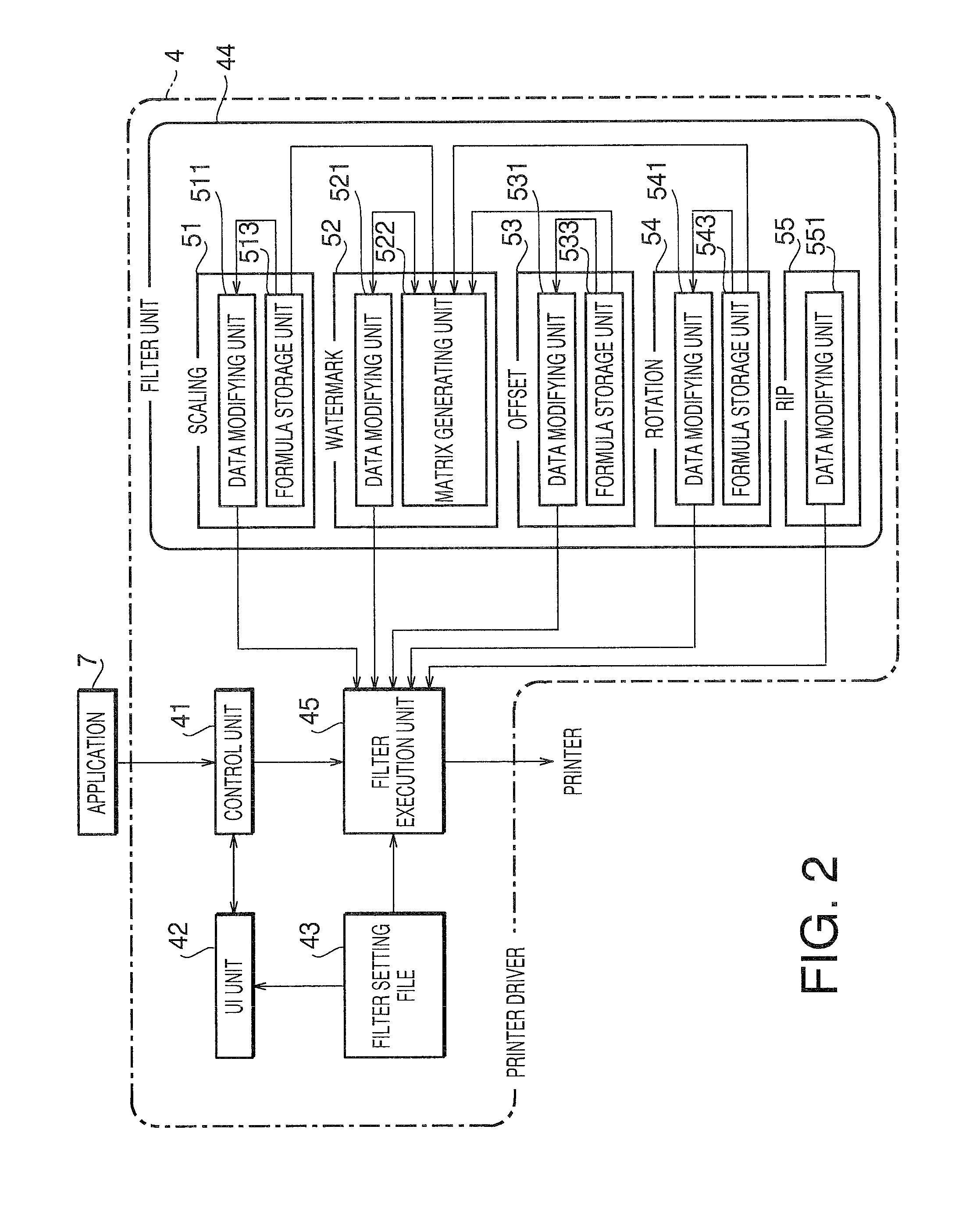
The patent describes an improved printer driver that allows users to modify the execution order of functional filters without affecting other users. The driver includes a group of filters that execute a modifying process for printing job data. The specific filter is provided with a conversion formula acquiring unit to inquire other filters and an additional information arranging unit to determine the arrangement of the additional information based on the conversion formula. This allows users to execute a desired modifying process without affecting the print job of another user.

Problems solved by technology

However, the conventional printer driver as described above has a problem as follows.
Therefore, if a certain user changes the order of execution of the functional filters and does not restore the order, another user may obtain unexpected print result due to the changed order of execution of the functional filters.
That is, a normal user is not allowed to change the order of execution of the functional filters.

Method used


Image

  • Apply conversion formula to functional filters executed in sequence for modifying print job
  • Apply conversion formula to functional filters executed in sequence for modifying print job
  • Apply conversion formula to functional filters executed in sequence for modifying print job

Examples


concrete example 1

[0095]FIG. 15 shows a concrete example 1. In this concrete example 1, it is assumed that scaling (magnification) is 1.25, an offset is 100 dots in an X direction, and a rotation is 90 degrees. Further, the scaling and the offset are to be applied to the watermark, whereas the rotation is not.

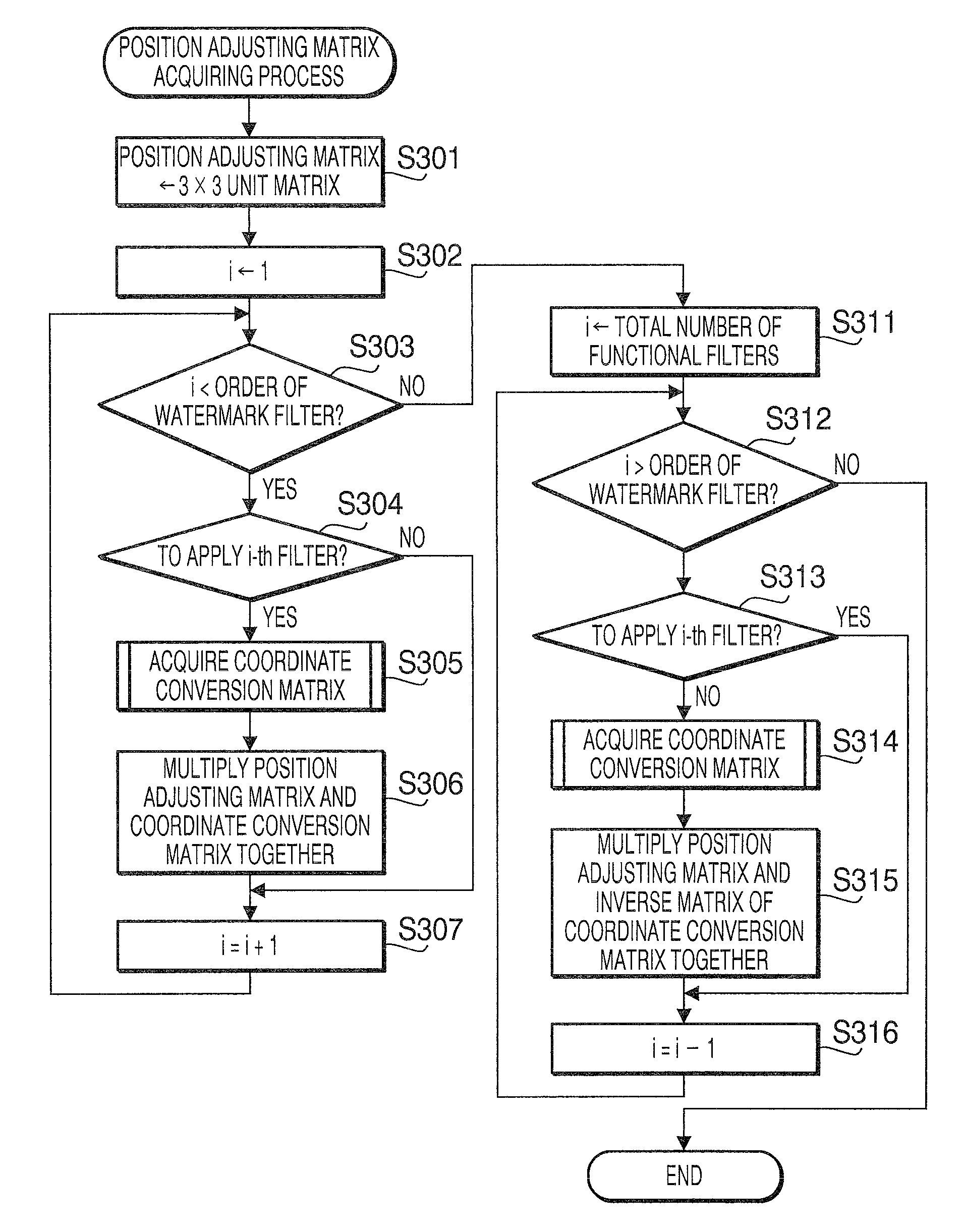
[0096]With the above setting, a matrix as shown in FIG. 16 is obtained from the functional filters 51, 53 and 54. Among them, the offset and rotation are the functional filters executed after the watermark, the inverse matrix of the acquired matrix is used. In this case, the position adjusting matrix is expressed as follows (see formula 1).

[0097](01-1000-105000001)⁢(1.250001.250001)=(01.25-1000-1.2505000001)(1)

[0098]That is, a matrix obtained from the functional filter 51 for scaling which is to be applied to the watermark is multiplied with an inverse matrix of a matrix obtained from the functional filter 54 for rotation which is not to be applied to the watermark to obtain the position adjusti...

concrete example 2

[0099]FIG. 2 shows a concrete example 2. In this example, it is assumed that the scaling (magnification) is 0.8, the offset is −200 dots in the Y direction, and the rotation is 45 degrees. The scaling is to be applied to the watermark, whereas the offset and rotation are not to be applied to the watermark.

[0100]With the above setting, a matrix as shown in FIG. 18 is obtained from the functional filters 51, 53 and 54. Among the functional filters, ones for the offset and the rotation are the functional filters executed after the watermark. Therefore, for these functional filters, inverse matrixes are used, In this example, the position adjusting matrix is expressed as follows (formula 2).

[0101](10001200001)⁢(0.7070.707-1356-0.7070.707-2293001)⁢(0.80000.80001)=(0.5660.566-1536-0.5660.566-2093001)(2)

[0102]That is, a matrix obtained from the functional filter 51 for scaling which is to be applied to the watermark is multiplied with an inverse matrix of the matrix obtained from the funct...


PUM


Abstract

A print control device has a group of filters including at least two functional filters which execute a modifying process for modifying print job, a filter configuration storage that stores configuration information of the functional filter group, a filter execution unit which retrieves functional filters based on the filter configuration information and causes the retrieved functional filters to execute a modifying process of the print job data. The functional filter group includes a specific functional filter for modifying the print job data by adding additional information. The specific functional filter includes a conversion formula acquiring unit which acquires a conversion formula for converting the additional information corresponding to the modifying process executed by the other functional filters, and an additional information arranging unit for determining an arrangement of the additional information with respect to the print job modified by the other filters based on the conversion formula.

Description

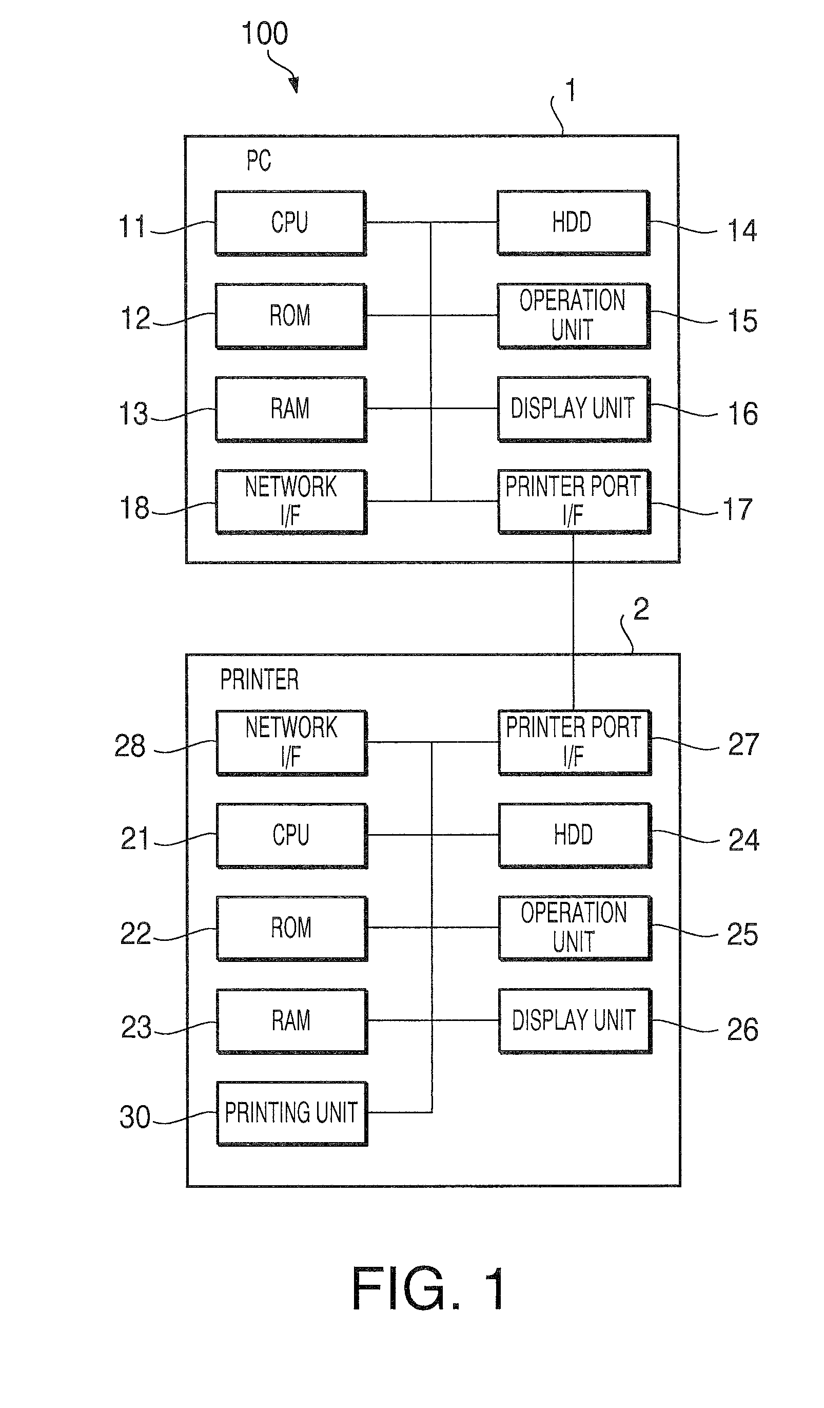
CROSS-REFERENCE TO RELATED APPLICATION[0001]This application claims priority under 35 U.S.C. §119 from Japanese Patent Application No. 2007-218100 filed on Aug. 24, 2007. The entire subject matter of the application is incorporated herein by reference.BACKGROUND[0002]1. Technical Field[0003]The present invention relates to a print control device and a recording medium storing a printer driver. Specifically, the invention relates to the print control device configured to modify print job data with use of functional filters, and the recording medium containing a printer driver to be installed in the print control device and to cause the print control device to function.[0004]2. Prior Art[0005]Generally, in the print control device for controlling a printer, a printer driver, which is a program, having functions of modifying the print job data is installed. As the functions of modifying the print job data, there are known a sorting function for changing the order of images to be printe...

Claims


Application Information

Patent Timeline
Patent Type & Authority Patents(United States)
IPC IPC(8): G06F15/00G06F3/12G06K1/00G06K15/02G06K15/00
CPCG06F3/1205G06F3/1276G06F3/1284G06F3/1204
Inventor MIYATA, YUJI
Owner BROTHER KOGYO KK
Learn More