Fall restraint equipment component and method for manufacturing the same

a technology for restraint equipment and components, which is applied in the direction of passenger handling equipment, bridges, transportation and packaging, etc., can solve the problem of increasing the cost of finished products

Active Publication Date: 2012-09-11
SAFERACK
View PDF43 Cites 11 Cited by
  • Summary
  • Abstract
  • Description
  • Claims
  • Application Information

AI Technical Summary

Problems solved by technology

Manufacturing components for fall restraint equipment in such a manner is a protracted process and increases the cost of the finished product.

Method used


Image

  • Fall restraint equipment component and method for manufacturing the same
  • Fall restraint equipment component and method for manufacturing the same
  • Fall restraint equipment component and method for manufacturing the same

Examples


Embodiment Construction

[0019]Reference will now be made in detail to presently preferred embodiments of the invention, one or more examples of which are illustrated in the accompanying drawings. Each example is provided by way of explanation of the invention, not limitation of the invention. In fact, it will be apparent to those skilled in the art that modifications and variations can be made in the present invention without departing from the scope or spirit thereof. For instance, features illustrated or described as part of one embodiment may be used on another embodiment to yield a still further embodiment. Thus, it is intended that the present invention covers such modifications and variations as come within the scope of the appended claims and their equivalents.

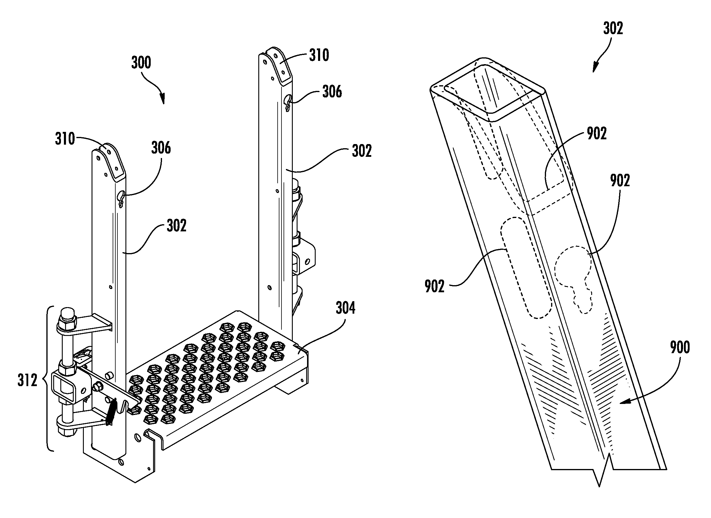
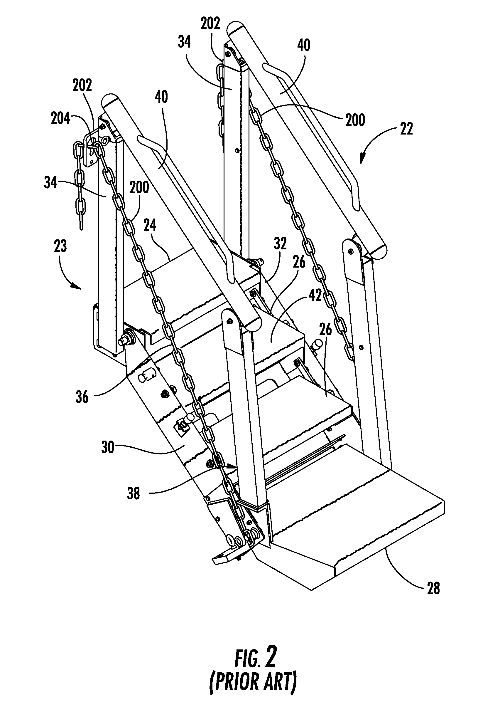
[0020]FIGS. 3 and 4 illustrate a base tread 300, which may be substituted for the base tread 23 of gangway 22 (FIG. 2). Additional information regarding the construction and operation of gangways is contained in U.S. patent application Ser. No...


PUM

PropertyMeasurementUnit
thicknessesaaaaaaaaaa
sizeaaaaaaaaaa
heightaaaaaaaaaa

Abstract

A post to be used in conjunction with a gangway or other fall restraint equipment where the post defines an aperture having an upper portion and a lower portion such that the upper portion is configured to allow a link of a chain to pass there through while the lower portion allows the link to pass through in one orientation but prevents the link from passing through in a second orientation traverse to the first orientation.

Description

CLAIM OF PRIORITY[0001]The present application claims the benefit of the United States provisional patent application filed on Aug. 10, 2008 by Robert W. Honeycutt for COMPONENTS OF SAFETY EQUIPMENT AND METHODS FOR MANUFACTURING THE SAME (Ser. No. 61 / 087,732), the entire disclosure of which is incorporated by reference as if set forth verbatim herein.FIELD OF THE INVENTION[0002]The present invention relates generally to fall restraint equipment components. More particularly, the present invention relates to posts for gangways.BACKGROUND OF THE INVENTION[0003]FIG. 1 illustrates an example of fall restraint equipment comprising a stairwell 16, a platform 18, and a gangway 10. Stairwell 16 ascends to platform 18, where gangway 10 is connected. An optional cage 20 may be connected to gangway 10 if desired. In this example, the fall restraint equipment provides a user with access to a top 14 of a container 12 (such as a railway car). Gangway 10 may be configured to maintain a fixed orien...

Claims


Application Information

Patent Timeline
Patent Type & Authority Patents(United States)
IPC IPC(8): E01D1/00
CPCB63B27/14E04F11/112B21D39/06E04F11/04E04H17/14E04F11/00E04F11/181Y10T29/49826Y10T29/49936Y10T29/49947Y10T29/49996
Inventor HONEYCUTT, ROBERT W.MEFFERD, THOMAS A.
Owner SAFERACK
Why Eureka
Try Eureka