System and method for determining position within a wellbore

a wellbore and position technology, applied in the direction of surveying, directional drilling, borehole/well accessories, etc., can solve the problems of positioning tools not being well suited for determining, tool wear or other degradation of components within the wellbore, and undesirable mechanical wear, etc., to increase the pressure, increase the deviation of a curvature, increase the effect of pressur

Active Publication Date: 2012-09-18
HALLIBURTON ENERGY SERVICES INC
View PDF45 Cites 20 Cited by
  • Summary
  • Abstract
  • Description
  • Claims
  • Application Information

AI Technical Summary

Problems solved by technology

While some mechanical tools are suitable for interacting with a variety of downhole features, the tools may wear or otherwise degrade the components within the wellbore and / or may undergo an undesirable amount of mechanical wear in response to the use of the position tool.
Further, some position tools are not well suited for determining a position within a wellbore that comprises components having a wide range of internal bore diameters.

Method used


Image

  • System and method for determining position within a wellbore
  • System and method for determining position within a wellbore
  • System and method for determining position within a wellbore

Examples


Embodiment Construction

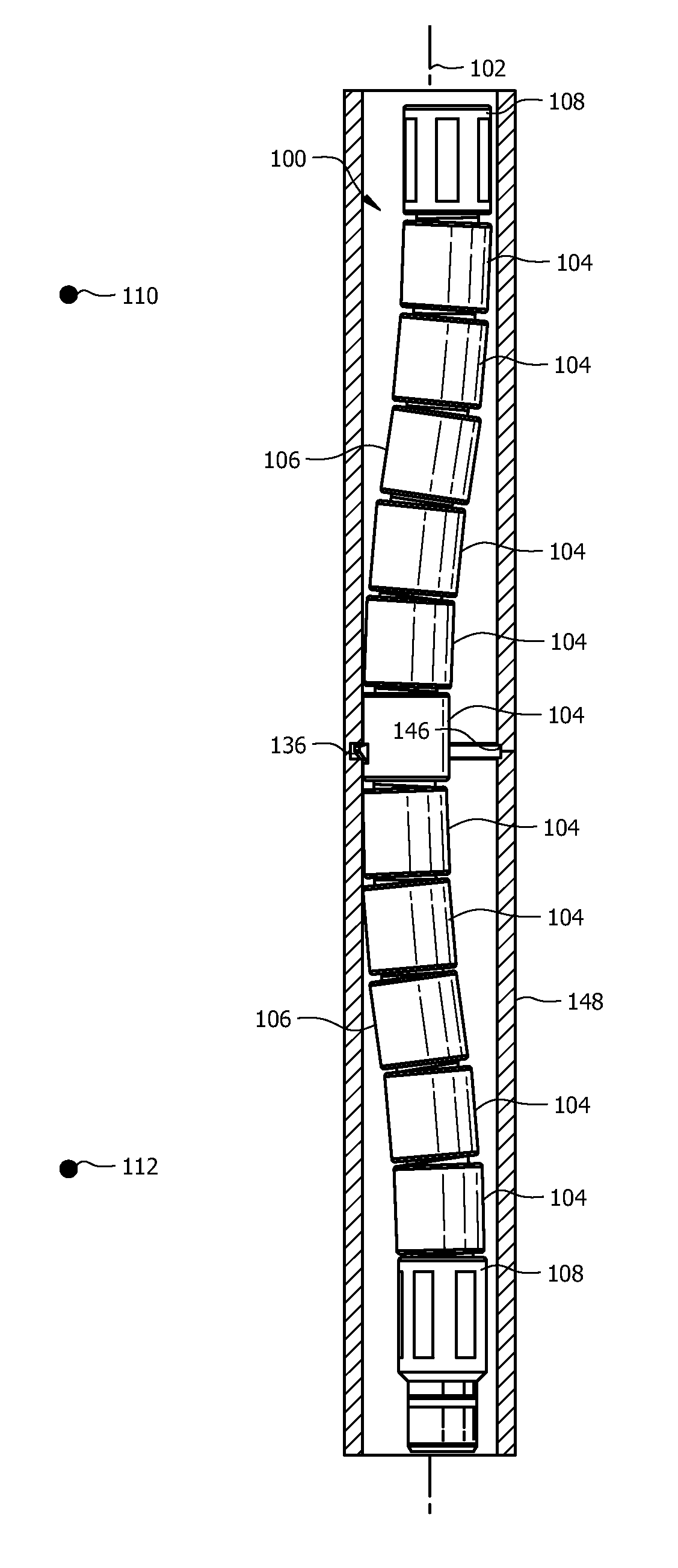
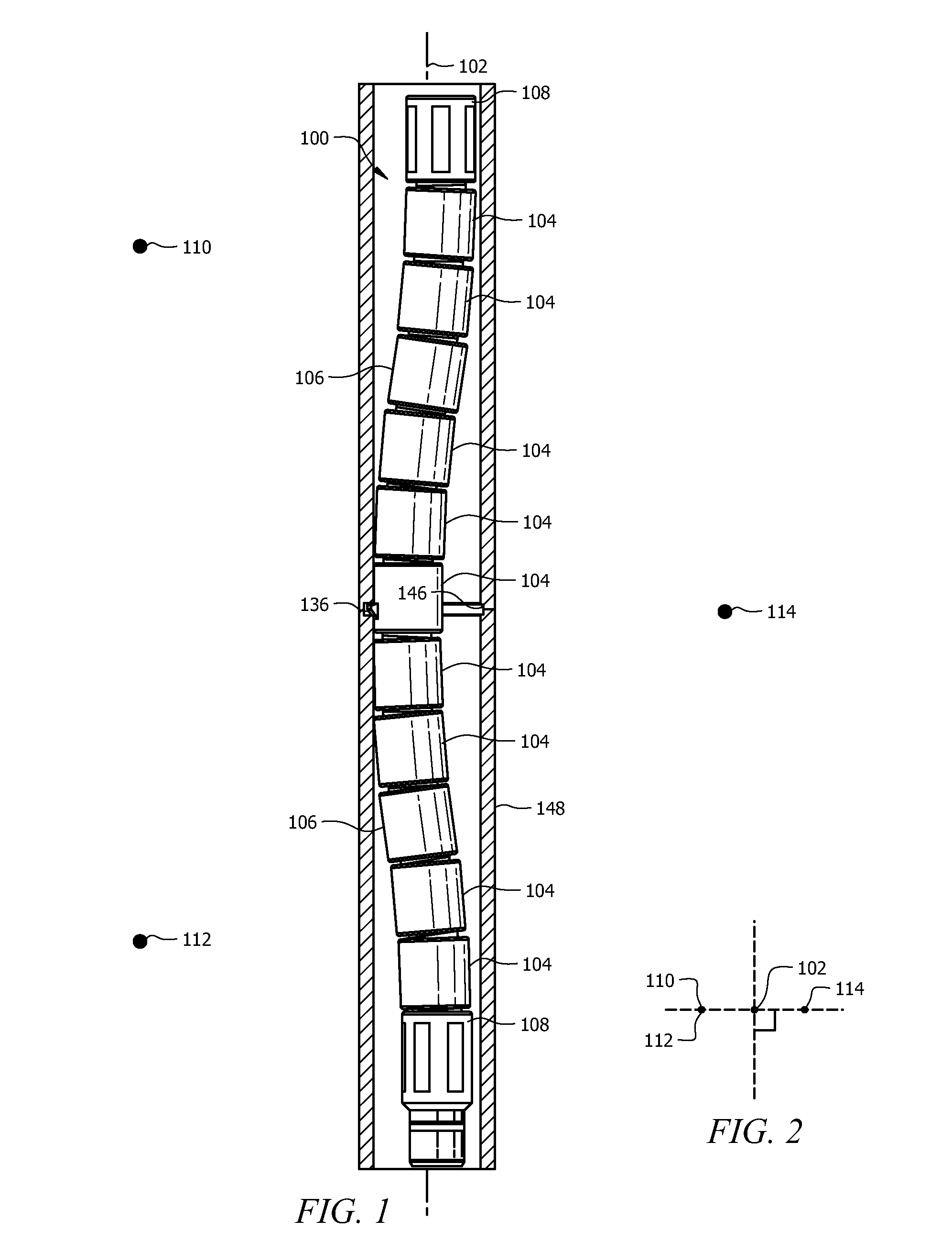
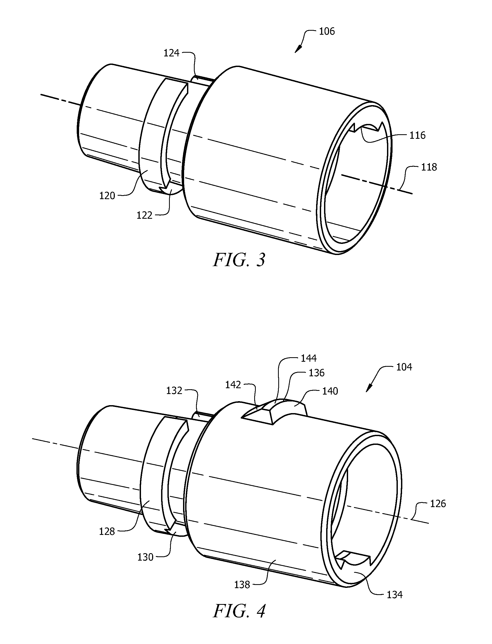
[0014]In the drawings and description that follow, like parts are typically marked throughout the specification and drawings with the same reference numerals, respectively. The drawing figures are not necessarily to scale. Certain features of the invention may be shown exaggerated in scale or in somewhat schematic form and some details of conventional elements may not be shown in the interest of clarity and conciseness.

[0015]Unless otherwise specified, any use of any form of the terms “connect,”“engage,”“couple,”“attach,” or any other term describing an interaction between elements is not meant to limit the interaction to direct interaction between the elements and may also include indirect interaction between the elements described. In the following discussion and in the claims, the terms “including” and “comprising” are used in an open-ended fashion, and thus should be interpreted to mean “including, but not limited to . . . ”. Reference to up or down will be made for purposes of ...


PUM


Abstract

A method of locating a wellbore feature, comprising delivering a mechanical position determination tool into the wellbore, selectively causing an undulating curvature of the mechanical position determination tool in response to a change in a fluid pressure, moving the mechanical position determination tool along a longitudinal length of the wellbore, and sensing a change in resistance to continued movement of the mechanical position determination tool. A mechanical position location tool for a wellbore, comprising pressure actuated elements configured to cooperate to selectively provide an unactuated state in which the mechanical position location tool lies substantially along a longitudinal axis and the pressure actuated elements further configured to cooperate to selectively lie increasingly deviated from the longitudinal axis in response to a change in pressure applied to the mechanical position location tool.

Description

CROSS-REFERENCE TO RELATED APPLICATIONS[0001]None.STATEMENT REGARDING FEDERALLY SPONSORED RESEARCH OR DEVELOPMENT[0002]Not applicable.REFERENCE TO A MICROFICHE APPENDIX[0003]Not applicable.FIELD OF THE INVENTION[0004]This invention relates to systems and methods of determining a position within a wellbore.BACKGROUND OF THE INVENTION[0005]It is sometimes necessary to determine a position within a wellbore, for example, to accurately locate a wellbore servicing tool. A variety of position tools exist for determining a position within a wellbore. Some tools are configured to enable determination of a position within a wellbore by inserting the tool into the wellbore and causing mechanical interaction between the position tool and casing collars, pipe collars, and / or other downhole features within the wellbore. While some mechanical tools are suitable for interacting with a variety of downhole features, the tools may wear or otherwise degrade the components within the wellbore and / or ma...

Claims


Application Information

Patent Timeline
Patent Type & Authority Patents(United States)
IPC IPC(8): E21B47/09E21B17/20E21B43/00E21B7/08E21B23/04
CPCE21B23/03E21B47/0915E21B47/09E21B47/098
Inventor SURJAATMADJA, JIM B.BAILEY, MICHAELHUNTER, TIMOTHY H.
Owner HALLIBURTON ENERGY SERVICES INC
Why Eureka
Try Eureka