Means for creating field configurable bridge, fracture or soluble insert plugs

Inactive Publication Date: 2012-09-18
BEAR CLAW TECH LLC
View PDF200 Cites 136 Cited by
  • Summary
  • Abstract
  • Description
  • Claims
  • Application Information

AI Technical Summary

Benefits of technology

[0010]It has been recognized that it would be advantageous to develop a field-configurable bridge, fracture or soluble insert plug made primarily from metal alloys and composite materials. In addition, it has been recognized that it would be advantageous to develop a plug in which the upper portion of the mandrel (aka top mandrel) is installed via a threaded or other mechanical connection. In addition, it has been recognized that it would be advantageous to develop a plug that transfers loa

Problems solved by technology

One disadvantage with some prior plugs is that they must be shipped from the factory in the configuration in which they will be used in the well.
Unfortunately, the well operator does not often know which plugs he wants installed at each level until he evaluates the well's response to the frac operations.
Therefore, t

Method used


Image

  • Means for creating field configurable bridge, fracture or soluble insert plugs
  • Means for creating field configurable bridge, fracture or soluble insert plugs
  • Means for creating field configurable bridge, fracture or soluble insert plugs

Examples


Embodiment Construction

)

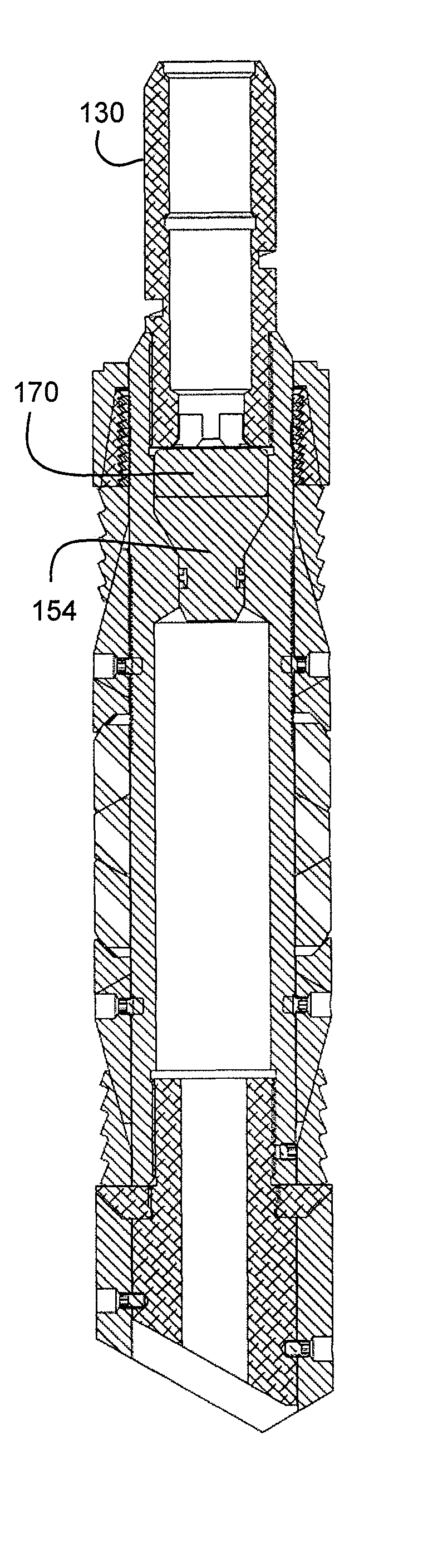
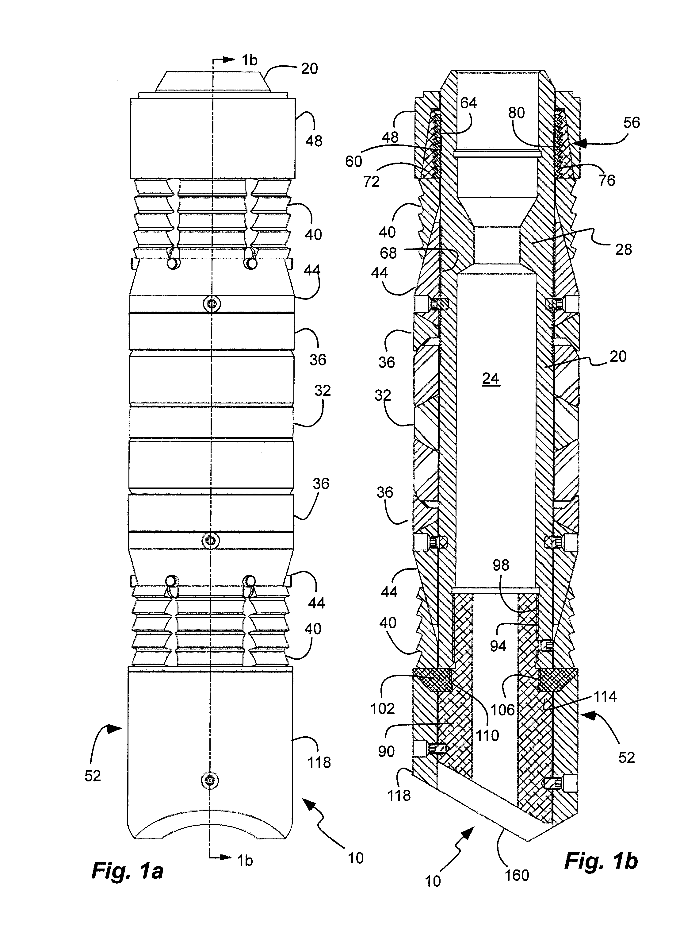
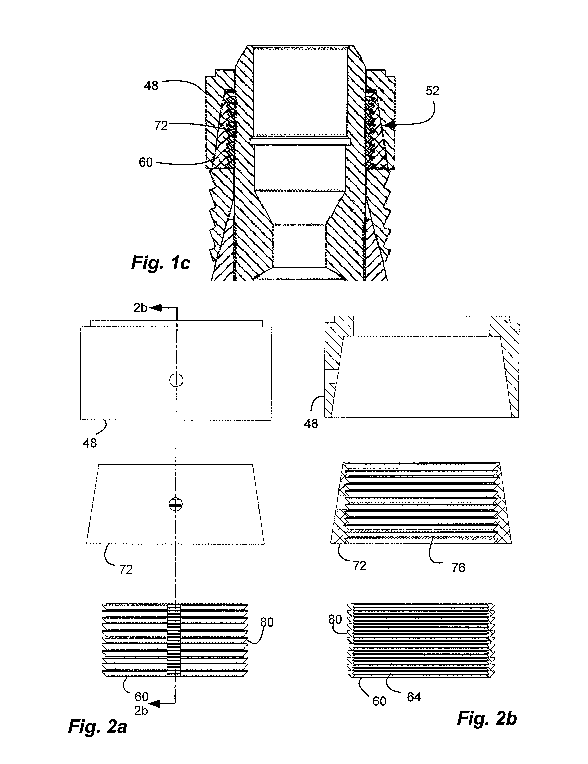
[0032]As illustrated in FIGS. 1a-3b, a plug device or mandrel assembly, indicated generally at 10, in an example implementation in accordance with the invention is shown for use in a pipe or casing of an oil or gas well. The plug 10 can be configured as a bridge plug to restrict flow in either direction (up and down), a fracture (“frac”) plug to restrict flow in one direction (typically down), or a soluble insert plug that begins as a bridge plug, but then transitions to a frac plug after a predetermined time or condition in the well. Various aspects of such plugs are shown in U.S. patent application Ser. Nos. 11 / 800,448; 12 / 353,655; 12 / 253,319; and 12 / 253,337; which are herein incorporated by reference.

[0033]The plug 10 includes a center mandrel 20 that can be made of aluminum. The mandrel 10 holds various other components which allow it to be coupled to a setting tool that is lowered into the pipe of the well. Thus, the mandrel has an outer diameter less than an inner diameter of...


PUM


Abstract

A plug for a pipe in an oil or gas well includes a packer, a slip ring and a cone disposable on a mandrel and pressed between an upper push sleeve and a lower anvil on the mandrel. The plug can be field configurable with a frac plug kit, a bridge plug kit and a soluble insert plug kit. A pair of concentric locking rings is disposed between the push sleeve and the mandrel with an outer annular cone with an outer conical shape tapered upwardly and inwardly.

Description

PRIORITY CLAIM[0001]This is a continuation-in-part of U.S. patent application Ser. No. 12 / 353,655, filed on Jan. 14, 2009 now U.S. Pat. No. 8,127,856, which claims priority to U.S. Provisional Application Ser. No. 61 / 089,302, filed Aug. 15, 2008, which are hereby incorporated herein by reference in their entirety.[0002]Priority is claimed to copending U.S. Provisional Patent Application Ser. No. 61 / 230,345, filed Jul. 31, 2009, which is hereby incorporated herein by reference in its entirety.RELATED APPLICATIONS[0003]This is related to U.S. patent application Ser. Nos. 11 / 800,448; 12 / 353,655; 12 / 253,319; and 12 / 253,337; which are hereby incorporated herein by reference in their entirety.BACKGROUND[0004]1. Field of the Invention[0005]The present invention relates generally to bridge and fracture plugs used in oil and gas wells.[0006]2. Related Art[0007]Just prior to beginning “production,” oil and gas wells are completed using a complex process involving explosive charges and high pr...

Claims


Application Information

Patent Timeline
IPC IPC(8): E21B34/00
CPCE21B33/1294E21B33/134E21B43/26
Inventor VOGEL, JASON JONNISH, RANDALL WILLIAMSJONES, RANDY ARTHUR
Owner BEAR CLAW TECH LLC
Why Eureka
Try Eureka