Shift-by-wire system

a technology of wires and shifters, applied in the direction of mechanical control devices, process and machine control, instruments, etc., can solve the problems of difficult to change the shift range of the automatic transmission, the release of the p range may be difficult, and the inability to secure the parking of the vehicle, etc., to achieve convenient vehicle relocation and secure parking.

Active Publication Date: 2012-10-09
TOYOTA JIDOSHA KK
View PDF25 Cites 16 Cited by
  • Summary
  • Abstract
  • Description
  • Claims
  • Application Information

AI Technical Summary

Benefits of technology

[0008]Thus, it is an objective of the present exemplary embodiment to provide a shift-by-wire system, which enables secure parking of a vehicle and easy relocation of the vehicle even when an abnormality occurs in an electric power source or an electric power supply system on the vehicle.

Problems solved by technology

Therefore, for example, when an abnormality occurs in an electric power source or an electric power supply system (e.g., battery exhaustion, breaking of a conductive line), it becomes difficult to change the shift range of the automatic transmission.
Thus, when the abnormality occurs in the electric power source or the electric power supply system, the secure parking of the vehicle may not be possible.
Furthermore, when the shift range is changed to the P range, releasing of the P range may possibly become difficult, and thereby towing of the vehicle may also become difficult.

Method used


Image

  • Shift-by-wire system
  • Shift-by-wire system
  • Shift-by-wire system

Examples


Embodiment Construction

[0018]An embodiment of the present invention will be described with reference to the accompanying drawings. In the following description, an electronic control unit will be abbreviated as an ECU.

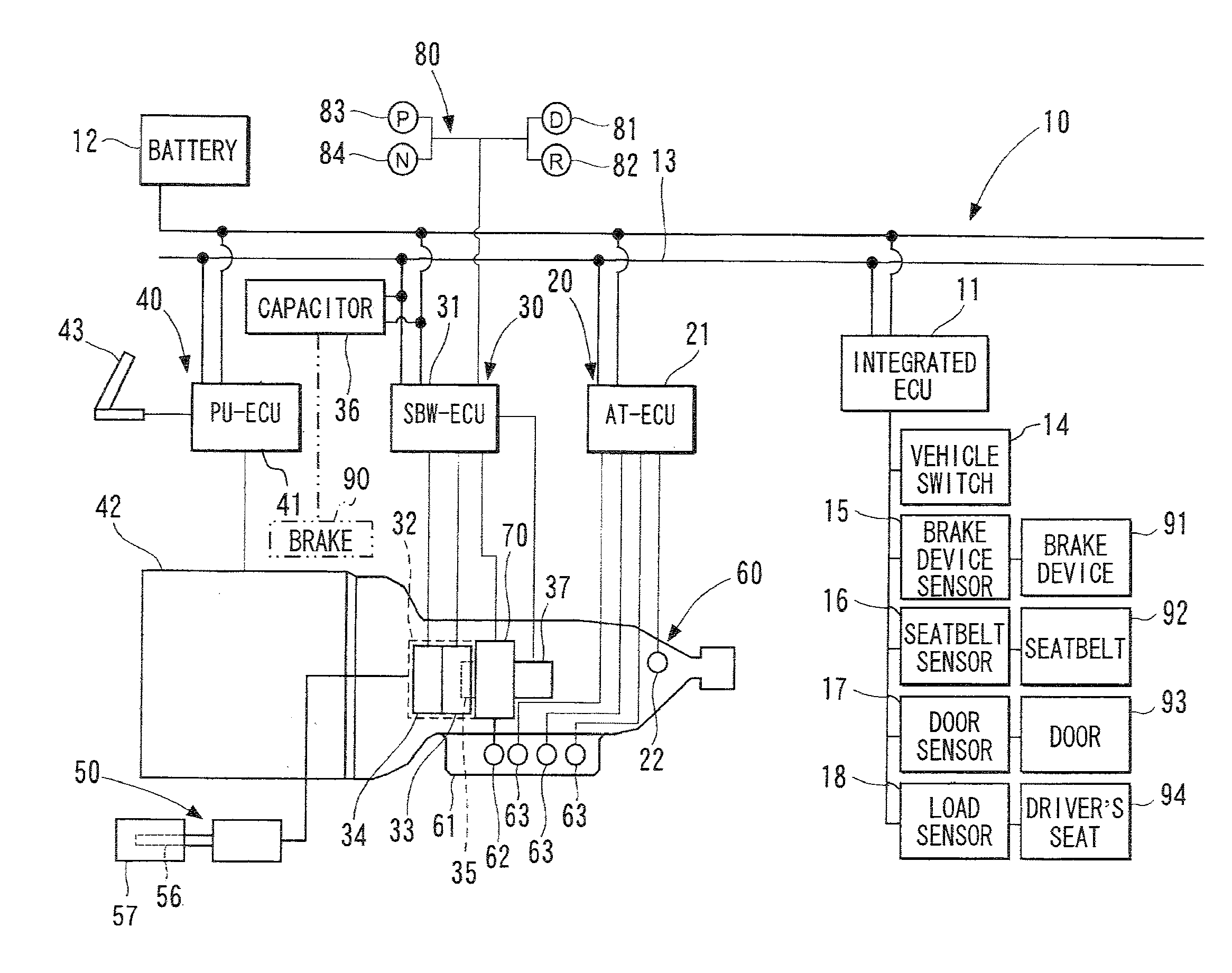
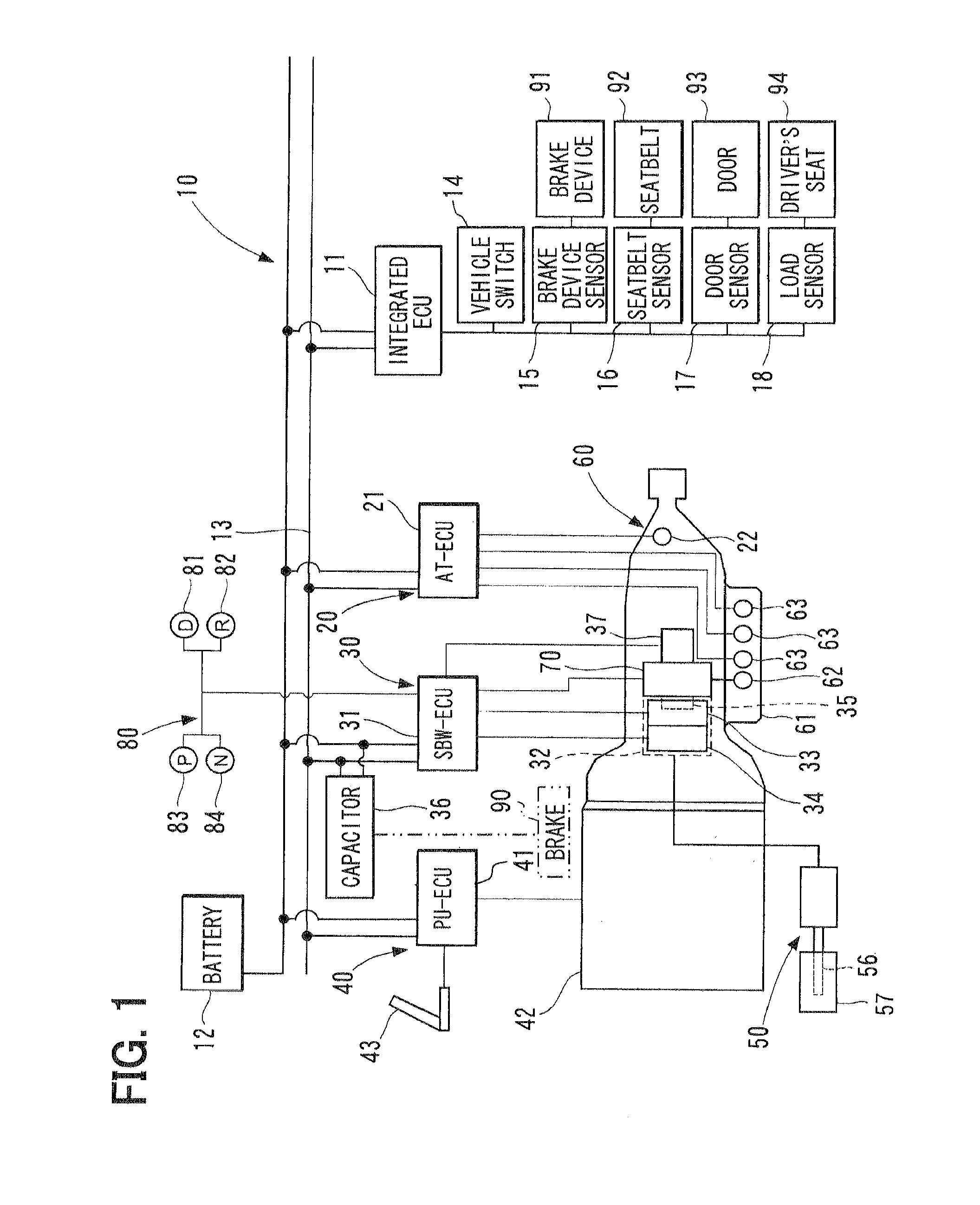
[0019]FIG. 1 illustrates a vehicle control system 10, which incorporates a shift-by-wire device in accordance with the embodiment of the present invention. For example, the vehicle control system 10 employed in, for example, a four-wheel vehicle includes an automatic transmission controller 20, a shift-by-wire device 30 (hereinafter, referred to as a SBW device), a power source controller 40, an integrated ECU 11 and a P range releasing arrangement 50.

[0020]The automatic transmission controller 20, the SBW device 30 and the power source controller 40 have an AT-ECU 21, an SBW-ECU 31 and a PU-ECU 41, respectively Each of the integrated ECU 11, the AT-ECU 21, the SBW-ECU 31 and the PU-ECU 41 is an electronic device, which includes a microcomputer as its main component. The integrated ECU 11, t...


PUM


Abstract

A shift-by-wire (SBW) device includes a capacitor, which stores electric power. When an abnormality occurs in a battery or an electric power supply system, an actuator of the SBW device receives electric power from the capacitor and changes a shift range of an automatic transmission to a P range at least once. Furthermore, when a lever of a P range releasing arrangement is operated, the P range of the automatic transmission is released.

Description

CROSS REFERENCE TO RELATED APPLICATION[0001]This application is based on and incorporates herein by reference Japanese Patent Application No. 2007-12821 filed on Jan. 23, 2007.BACKGROUND OF THE INVENTION[0002]1. Field of the Invention[0003]The present invention relates to a shift-by-wire system, which changes a shift range of an automatic transmission of a vehicle.[0004]2. Description of Related Art[0005]In recent years, in the field of vehicle control technique, by-wire systems have increasingly been employed. In general, the by-wire system electrically controls a corresponding actuator, which changes a corresponding operational state of the vehicle, based on a command of an occupant of the vehicle. For example, a shift-by-wire system, which changes a shift range of an automatic transmission of the vehicle based on a command of the occupant of the vehicle, is known (see, for example, Japanese Unexamined Patent Publication No. 2001-271917 and Japanese Unexamined Patent Publication N...

Claims


Application Information

Patent Timeline
Patent Type & Authority Patents(United States)
IPC IPC(8): B60K17/00F16H61/28F16H63/34
CPCF16H61/12F16H61/32F16H2061/122F16H2061/1292Y10T74/19251F16H2061/2876Y10T74/20085Y10T74/2003F16H2061/326
Inventor KIMURA, KIYOSHIYOSHIYAMA, SHIGERUITOH, TAKUNOZAKI, YOSHINOBUKAMADA, ATSUSHI
Owner TOYOTA JIDOSHA KK
Why Eureka
Try Eureka