Robot system and robot

a robot and robot technology, applied in the field of robot systems and robots, can solve the problems of difficult to stabilize the center of gravity, high center of gravity, and the robot may fall over with the ceiling frame, and achieve the effect of widening the working range of the first robo

Active Publication Date: 2018-06-07
SEIKO EPSON CORP
View PDF15 Cites 3 Cited by
  • Summary
  • Abstract
  • Description
  • Claims
  • Application Information

AI Technical Summary

Benefits of technology

[0012]Accordingly, since a relative position of the positioning unit to the first cell is determined, it is possible to omit the work of installing the cell such that the first robot is positioned in an appropriate position with respect to the positioning unit. Therefore, it is possible to easily relocate the first cell which is provided with the first robot. Since the positioning unit is provided in the inner portion of the first cell, it is possible to further reduce the size of the robot system in comparison with a case in which the positioning unit is provided on the outer portion of the first cell.
[0088]Accordingly, for example, it is possible to grip the target object on the second transporter using the first robot, move the target object to the first transporter, and mount the target object. In this manner, it is possible to widen the working range of the first robot.

Problems solved by technology

Since the robot which is described in JP-A-2010-137321 is provided on a ceiling frame, the center of gravity is high and there is a concern that the robot may fall over together with the ceiling frame.
In JP-A-2010-137321, although two robot cells are lined up in close proximity, each of the robot cells is installed individually, and thus, it is difficult to stabilize the center of gravity.
As a result, it is difficult to stably drive the robot arm.
Therefore, it is possible to reduce a decrease in the overall productivity of the robot system.

Method used


Image

  • Robot system and robot
  • Robot system and robot
  • Robot system and robot

Examples


first embodiment

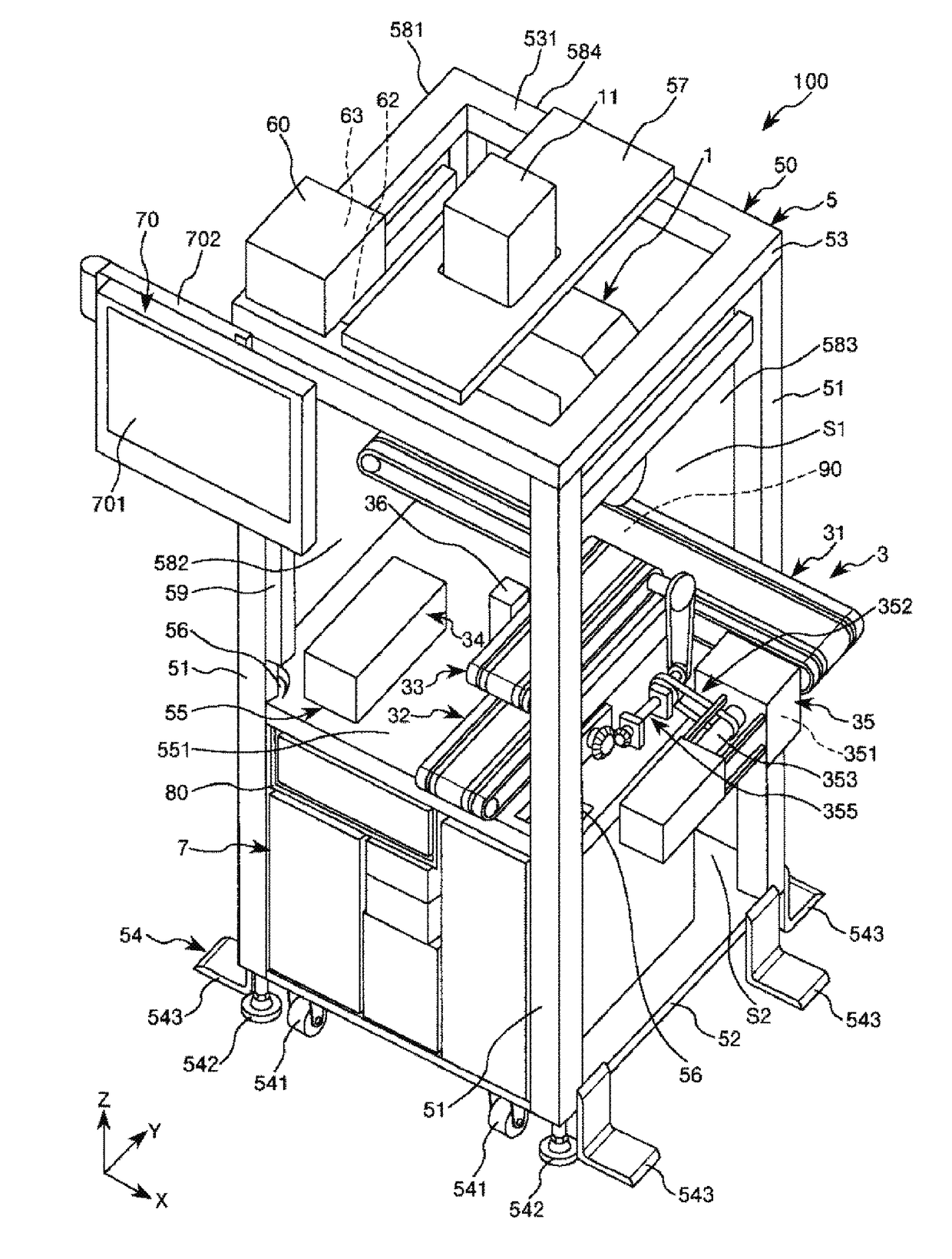
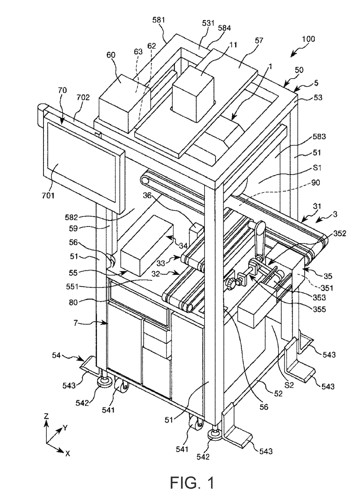
[0110]FIG. 1 is a perspective view illustrating a first embodiment of a robot system according to the invention. FIG. 2 is a front view of the robot system illustrated in FIG. 1. FIG. 3 is a rear view of the robot system illustrated in FIG. 1. FIG. 4 is a left-side view of the robot system illustrated in FIG. 1. FIG. 5 is a right-side view of the robot system illustrated in FIG. 1. FIG. 6 is a diagram of the robot illustrated in FIG. 1. FIG. 7 is a schematic diagram of the robot illustrated in FIG. 6. Each of FIGS. 8 and 9 is a side view of the robot illustrated in FIG. 6. FIGS. 10A-10E are diagrams for describing the operations of the robot illustrated in FIG. 6. FIG. 11 is a diagram illustrating a movement path of a distal end portion of a robot arm which is included in the robot illustrated in FIG. 6. FIG. 12 is a plan view of a transport unit illustrated in FIG. 1. FIG. 13 is a perspective view of the transport unit illustrated in FIG. 1. FIGS. 14A and 14B are diagrams illustrat...

second embodiment

[0228]FIG. 15 is a diagram illustrating the second embodiment of a robot system according to the invention. In FIG. 15, the illustration of the gas supply unit and the display operation unit is omitted.

[0229]Hereinafter, a description will be given of the second embodiment with reference to the drawings; however, the description will be given centered on the points of difference with the above-described embodiment, omitting the description of items which are the same.

[0230]In the robot system of the present embodiment, a changing mechanism is included which differs from that of the first embodiment.

[0231]The robot system 100 which is illustrated in FIG. 15 includes a changing mechanism 40 which changes the installation height of the robot 1 with respect to the cell 5. The changing mechanism 40 includes two spacers 411 which are provided between the ceiling portion 53 and the attachment plate 57 of the cell 5. By attaching the spacers 411, it is possible to change a separation distan...

third embodiment

[0234]FIGS. 16A and 16B are diagrams illustrating the third embodiment of a robot system according to the invention. FIG. 16A is a front view and FIG. 16B is a bottom view.

[0235]Hereinafter, a description will be given of the third embodiment with reference to the drawings; however, the description will be given centered on the points of difference with the above-described embodiments, omitting the description of items which are the same.

[0236]In the robot system of the present embodiment, a configuration is adopted such that it is possible to provide a weight and this is different from the first embodiment.

[0237]In the robot system 100 which is illustrated in FIG. 16A, a box-shaped support portion 22 which hangs down from the reverse surface of the base portion 52 is attached below the base portion 52 of the cell 5. The second side surface portion 582 side of the support portion 22 is open. It is possible to insert and remove a weight 20 inside the support portion 22 from the opene...


PUM


Abstract

A robot system and a robot are capable of easily defining a position of a target object with respect to a robot. The robot system includes a first robot, a first cell which is provided with the first robot and is capable of moving, and a positioning unit which is provided in an inner portion of the first cell and positions a target object.

Description

BACKGROUNDTechnical Field[0001]The present invention relates to a robot system and a robot.Background Art[0002]In the related art, a robot system including a robot which is provided with a robot arm, and a cell which supports the robot is known. In the robot arm with which the robot is provided, a plurality of arms (arm members) are connected with each other via joint portions, and, for example, a hand is attached as an end effector to the arm of the most distal end side (the most downstream side). The joint portions are driven by motors and the arms move rotationally through the driving of the joint portions. The robot grips a target object using the hand, for example, moves the target object to a predetermined place and performs work such as assembly.[0003]As an example of such a robot system, JP-A-2012-187663 discloses a robot system (a production device) including a robot having two robot arms and a cell which supports the robot.[0004]For example, in a case in which such a robot...

Claims


Application Information

Patent Timeline
Patent Type & Authority Applications(United States)
IPC IPC(8): B25J9/16B25J9/00B25J21/00
CPCB25J9/1682B25J9/0093B25J21/00B25J9/0084B23P19/04B23P21/00B25J9/0018
Inventor YOKOTA, MASATOIIJIMA, SHIGUMA
Owner SEIKO EPSON CORP
Why Eureka
Try Eureka