Look ahead vehicle suspension system

a vehicle suspension and look-ahead technology, applied in the field of automobiles, can solve the problems of fully limited the performance of the prior suspension system, and the distinct disadvantage of being reactive to the motion of the tires/wheels with respect to the body, so as to improve safety and comfort, and reduce the meeting of tires

Active Publication Date: 2012-10-09
ENPULZ
View PDF22 Cites 60 Cited by
  • Summary
  • Abstract
  • Description
  • Claims
  • Application Information

AI Technical Summary

Benefits of technology

[0005]Various aspects of the present invention are found in an active vehicle suspension system of the present invention. The active vehicle suspension system of the present invention senses an appearing roadway hazard and actively alters the behavior of its suspension system in preparation of an expected meeting with the road hazard. The active vehicle suspension system control therefore prepares the suspension system to effectively mitigate meeting of tires of the vehicle with the road hazard to cause the suspension system to absorb much of the shock caused by the meeting and the oscillations of the body (vehicle cabin) that the meeting would otherwise cause to provide improved safety and comfort to the people inside the cabin.
[0006]Embodiments of present invention provide active cruise control operation to provide better sensing capability of roadway conditions so as to enhance the safety of the cruise operation. The roadway hazards sensing operations of the present invention intercouple with the cruise control system to automatically override cruise control settings, alter the drive override cruise control settings, and also cause the automobile to actively brake in preparation for impact with the road hazard.
[0007]Some embodiments of the present invention provide multilevel decision making capability for a vehicular “sense and control mechanism” for the identification of each type of the roadway defects based on their width, depth, and height, which requires multilevel control (signal) for hazard mitigation, in a smooth manner, through a smoother adjustment of suspension fluid pressure for a jerk free cruise of vehicle over the roadway.

Problems solved by technology

Further, because it was disadvantageous for the motion of wheels to be coupled to one another via the suspension system, independent suspension systems were developed that allowed each tire / wheel to move independently from each other tire / wheel.
Each of these prior suspension systems has the distinct disadvantage of being reactive to the motion of the tires / wheels with respect to the body.
Such reactive behavior of the prior automobile suspension systems fully limited the performance that these suspension systems could achieve.

Method used


Image

  • Look ahead vehicle suspension system
  • Look ahead vehicle suspension system
  • Look ahead vehicle suspension system

Examples


Embodiment Construction

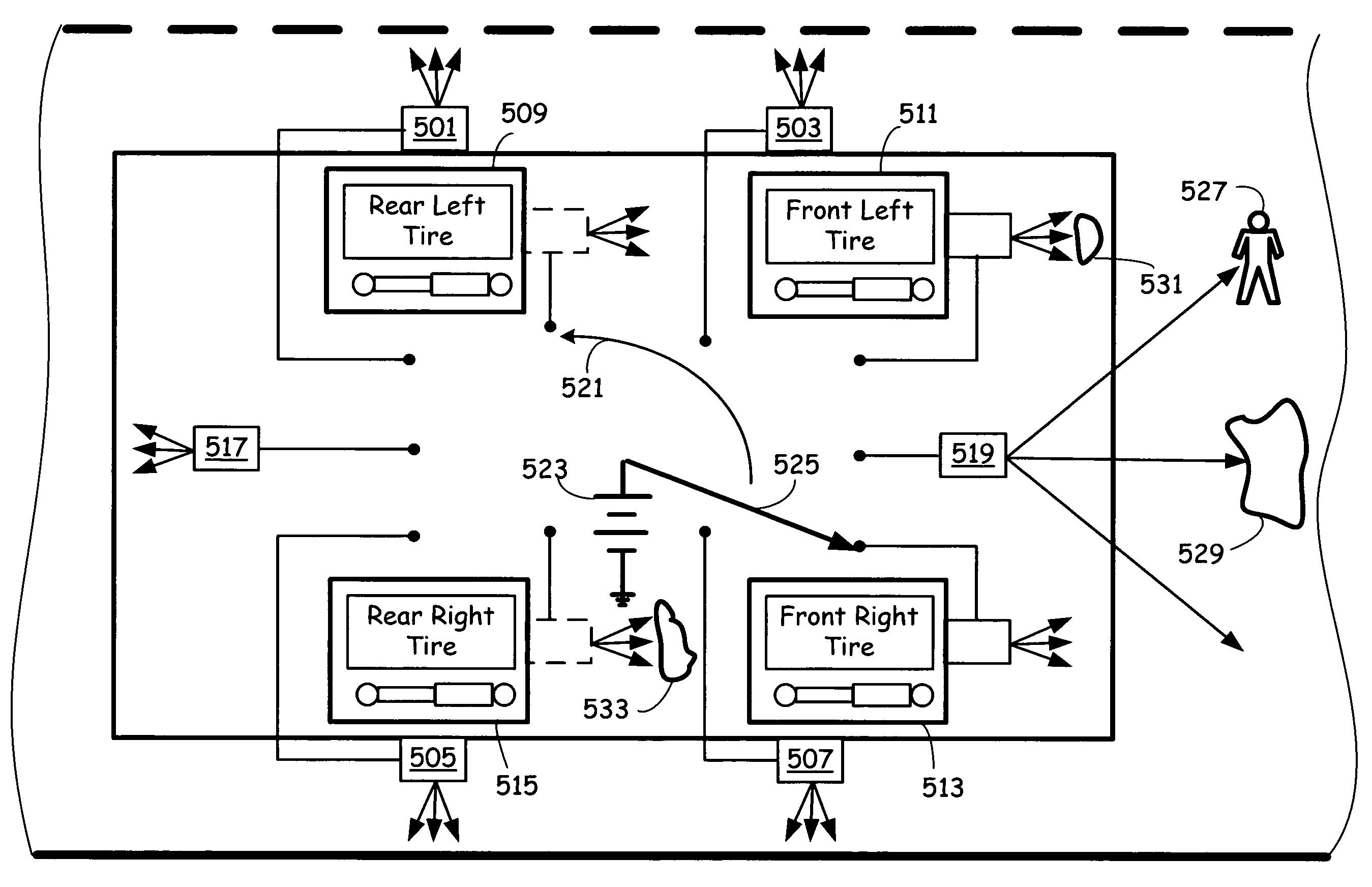
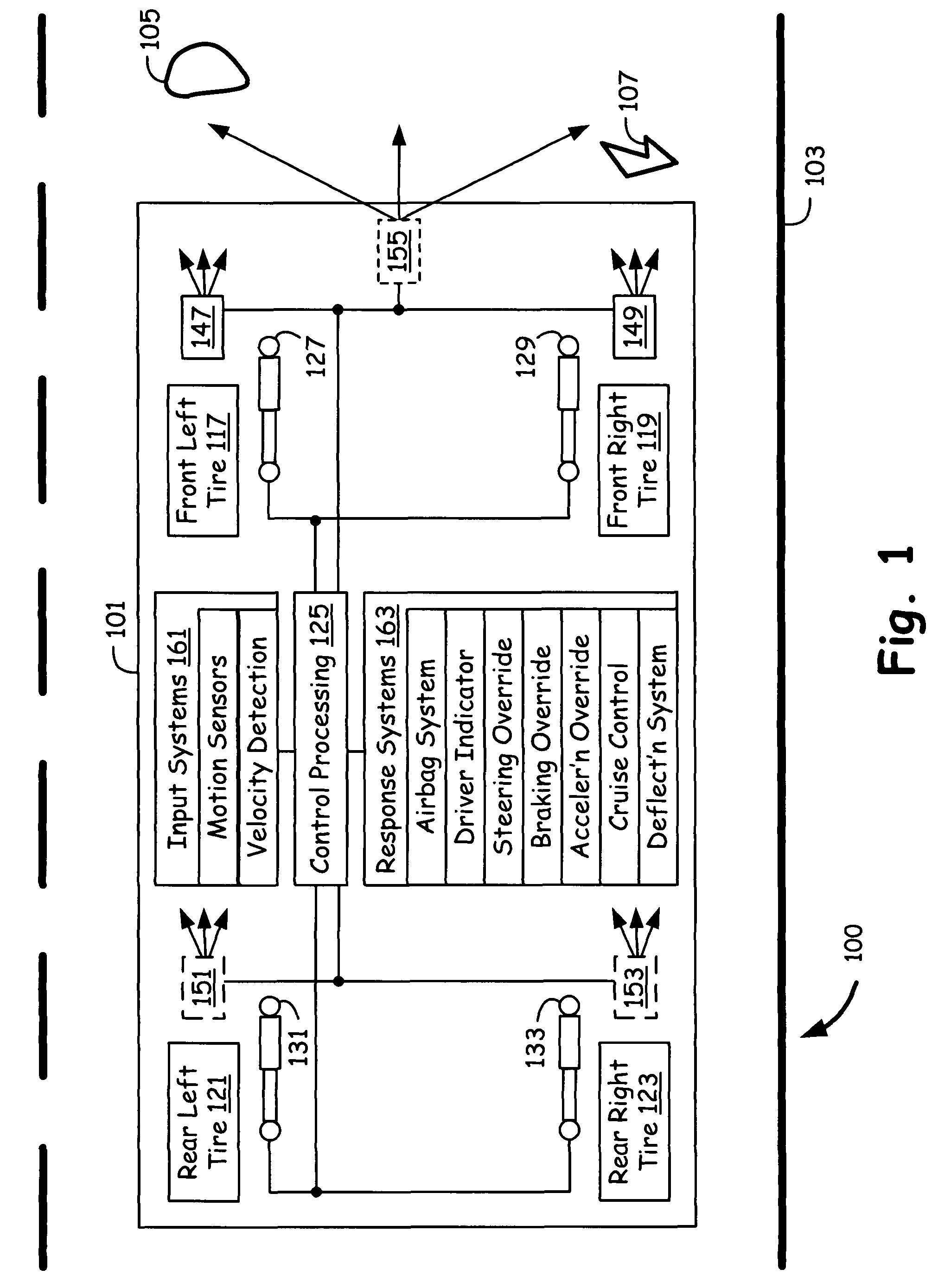
[0020]FIG. 1 is a traffic system 100, comprising a four wheeler vehicle 101 on a roadway 103, which has deployed the look ahead suspension technique, having a capability to visualize roadway defects such as potholes and bumps, 105, and obstacle 107 well ahead in anticipation, which can cause undesirable shocks and oscillations to the vehicle and hence discomforting people inside it. The suspension adjustment is done before vehicle physically coming in contact with the defects, to mitigate their effects.

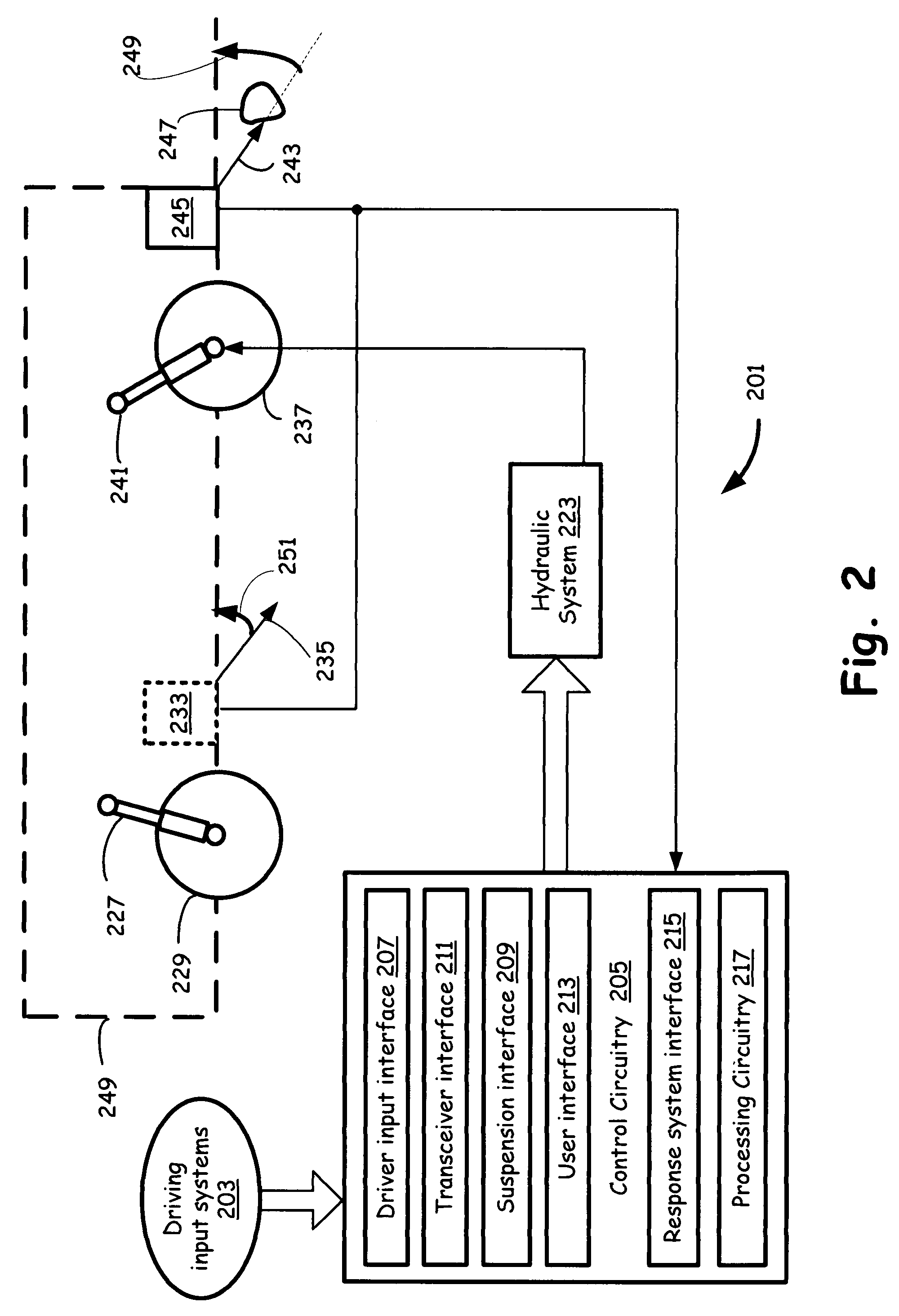
[0021]The front left tire assembly 117, is associated with a transceiver detector assembly 147, and further associated with an adjustable suspension 127. The transceiver 147 can transmit electromagnetic waves, according to an embodiment of the present invention, towards the roadway and receives the reflected wave, which is characterized by the roadway characteristics.

[0022]The front right tire assembly 119, is associated with a transceiver detector assembly 149, and further associated...


PUM


Abstract

An active suspension system senses roadway defects and adjusts an active and controllable suspension system of the vehicle before tires come in contact with the defect. The active suspension system identifies a type of defect or debris, e.g., pothole, bump, object, etc., along with the size, width, depth, and / or height information of the defect to more accurately control operation of the suspension system to prepare for, or avoid contact with the roadway defects and obstacles. Imaging techniques are employed to identify the defect or debris. Operation of a serviced cruise control system is controlled to enhance passenger safety and comfort.

Description

FIELD OF THE INVENTION[0001]This invention relates to automobiles and, more particularly, to suspension systems used in automobiles.BACKGROUND OF THE INVENTION[0002]Automobile (vehicle) suspension systems are generally known. An automobile suspension system isolates to some degree the tires and wheels of the automobile from the occupant-carrying body (vehicle cabin) of the automobile. Passive automobile suspension systems react when the surface upon which the automobile is traveling changes over distance and time. For example, when the tires of the automobile come in physical contact with a bump as the automobile travels over the bump, the suspension system reacts to partially isolate the relative motion of the tires from the body to minimize the impact upon the occupants of the vehicle. Likewise, when a tire passes over a pothole in the road, the tire drops into the pothole and the suspension system operates to isolate this relative motion of the tire from the body to minimize impa...

Claims


Application Information

Patent Timeline
Patent Type & Authority Patents(United States)
IPC IPC(8): B60G17/00G01S17/04
CPCB60W30/08B60G17/0165B60G17/0195B60G17/019G01S17/026B60W2550/306B60W2550/147B60W2710/20B60W50/14B60W2710/22B60G2400/821B60G2401/142B60W10/22B60W30/14B60W2710/18B60R21/0132B60G2800/91B60W30/18172B60G2800/982B60W2550/20B60W30/09B60W30/16B60G2800/162B60G2800/92B60W40/02B60G2800/96B60G2400/823B60W2552/35B60W2554/4041B60W2554/00G01S17/04B60G17/01908B60G17/01933B60G17/08B60G2800/925
Inventor BENNETT, JAMES D.
Owner ENPULZ
Why Eureka
Try Eureka