
Printing roll release mechanism

a technology of printing roll and release mechanism, which is applied in the direction of printing and other printing apparatuses, can solve the problems of difficult connection with pulling out or removing, and achieve the effect of ease and rapid tim

Active Publication Date: 2012-10-30
CUSTOM
View PDF8 Cites 1 Cited by
  • Summary
  • Abstract
  • Description
  • Claims
  • Application Information

AI Technical Summary

Benefits of technology

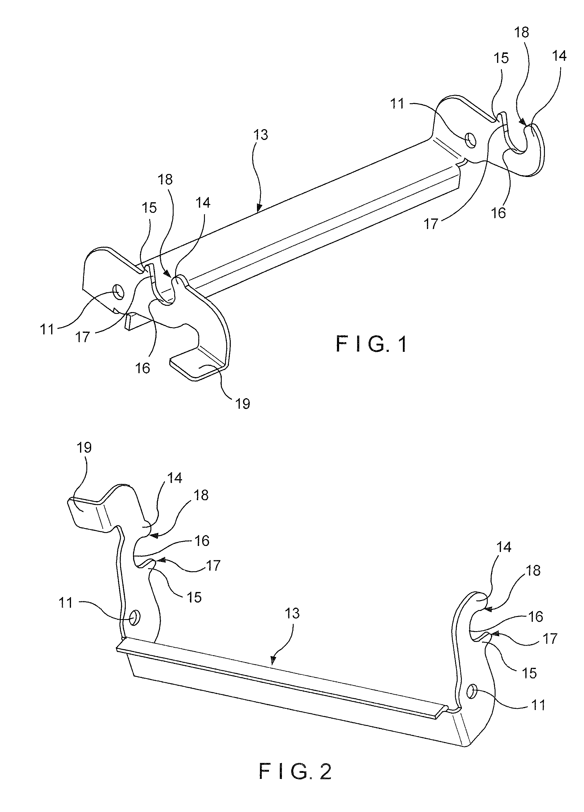
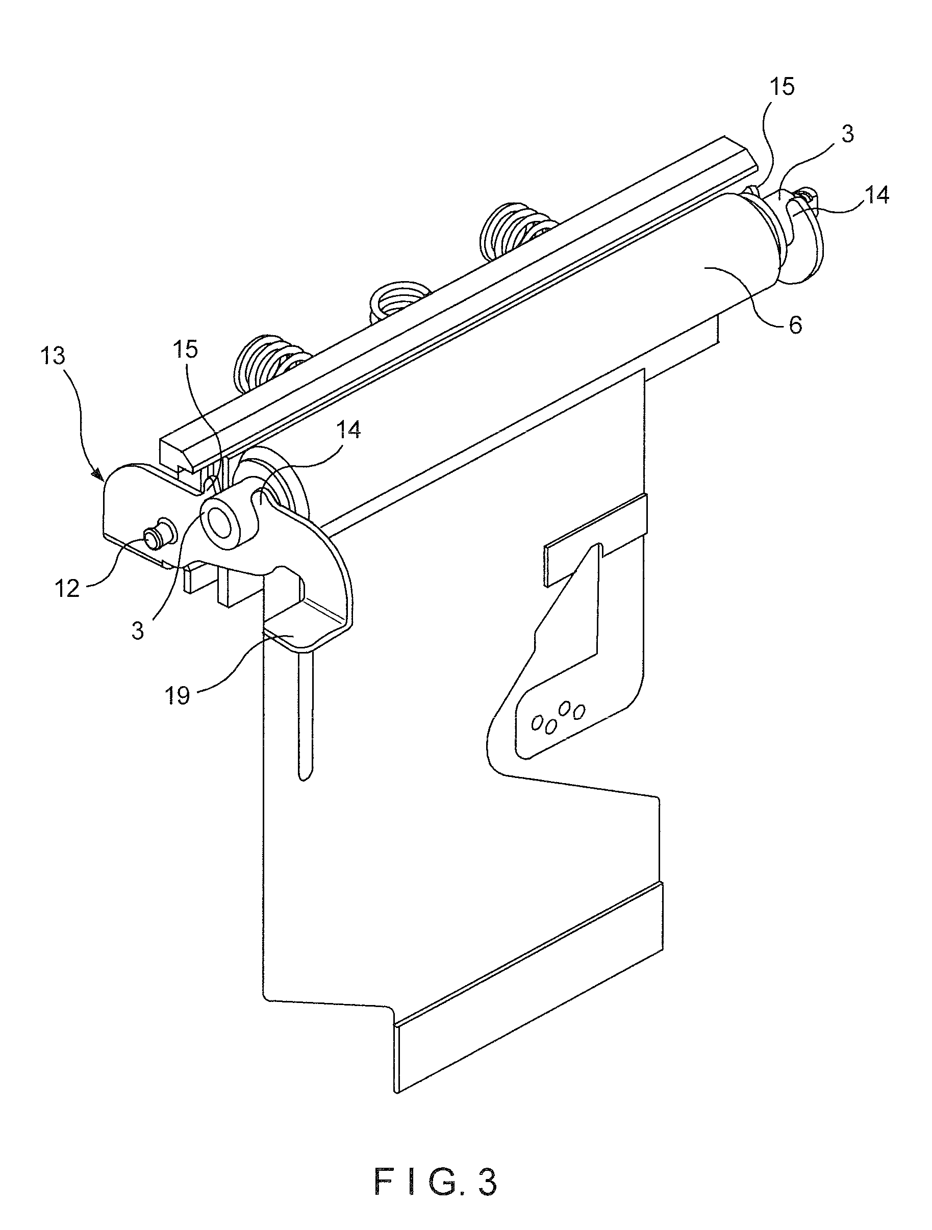
"The present invention provides an arrangement to easily and quickly remove the gummed printing roll from its seat in the thermal printer. This is achieved by providing freeing levers that are activated by a freeing tooth that works with pins and ferrules on the printing roll. The levers can be easily moved and used by any user, and the tooth pins and ferrules associated with the printing roll make the process easier and faster."

Problems solved by technology

In known thermal printer apparatus, difficulties arise in connection with the pulling out or removal of the gummed printing roll from the printer apparatus, as well as difficulties in connection with insertion of the gummed printing roll into the thermal printer apparatus.

Method used


Image

  • Printing roll release mechanism
  • Printing roll release mechanism
  • Printing roll release mechanism

Examples


Embodiment Construction

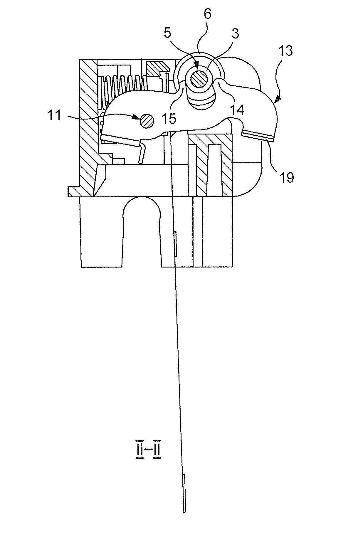
[0061]Referring now to the accompanying drawings and, more particularly, to FIG. 5, a printing roll release mechanism according to the invention comprises printing head holder for holding gummed printing roll 6, and which is provided with a pair of oppositely disposed spaced upper openings 2 for receiving shaft 5 which carries gummed printing roll 6. As also best seen in FIG. 4, shaft 5 supports gummed printing roll 6. Positioned on each end of shaft 5 is a pair of oppositely disposed ferrules 3 and washers 4, located between each ferrule 3 and gummed printing roll 6.

[0062]Each upper opening 2 which receives ferrule 3, see FIG. 6, is provided with an outline having an inside part with a substantially semi-circular cavity 7, see FIG. 6. One end of semi-circular cavity 7 is provided with a first extension on projection 8 in the form of a slanting part, slanting and extending towards the upper opening 2 and a second or vertical part 9 (as shown vertically in FIG. 5) and terminating at ...


PUM


Abstract

A printing roll release and retainer mechanism to facilitate the insertion of a printing roller into a printing head of a thermal printer and to facilitate the locking thereof to the printing head and to facilitate the removal of the printing roller from the printing head wherein a holder is provided for receiving and permitting withdrawal of the printing roller and a pair of oppositely spaced members is provided for to hold the shaft roller.A locking-release member is provided for the holder to facilitate locking of the roller to the printing head and removal therefrom, the oppositely spaced members have an arcuate configuration for receiving the shaft and is provided with a pair of portions extending from the ends of the arcuate configuration, the locking release member include spaced members with an arcuate configuration for receiving the shaft when the roller is inserted into the head, and a pair of members are provided for locking the roller to the printing head in one position of the locking-release member and for releasing the roller from the head in another position of the locking-release member.

Description

FIELD OF THE INVENTION[0001]This invention is concerned with a printing roll release mechanism for a thermal printer. More particularly, the present invention is concerned with a mechanical arrangement that provides for easy removal and insertion of a printing roll, preferably a gummed printing roll from and into the thermal printer which includes the printing roll release of the head in the thermal printer.DESCRIPTION OF THE PRIOR ART[0002]In present day thermal printers, the printing roll is fastened to a support apparatus that permits the gummed printing roll to rotate around its own longitudinal axis. In known thermal printer apparatus, difficulties arise in connection with the pulling out or removal of the gummed printing roll from the printer apparatus, as well as difficulties in connection with insertion of the gummed printing roll into the thermal printer apparatus.BRIEF SUMMARY OF THE INVENTION[0003]One of the features of the present invention is to provide an arrangement t...

Claims


Application Information

Patent Timeline
Patent Type & Authority Patents(United States)
IPC IPC(8): B41J15/00
CPCB41J11/04B41J15/042
Inventor CAMPANINI, ALBERTO
Owner CUSTOM
Learn More