
Machine for spreading fabric

a fabric machine and fabric technology, applied in the field of fabric machine, can solve the problems of reducing the spread speed, and limiting the speed of the fabri

Active Publication Date: 2021-03-30
MORGAN TECNICA
View PDF18 Cites 0 Cited by
  • Summary
  • Abstract
  • Description
  • Claims
  • Application Information

AI Technical Summary

Benefits of technology

The patent describes a machine for spreading fabric that can work with both lightweight and heavy fabrics using both the vertical drop and chute drop techniques, ensuring optimal speeds and easy switching between techniques. The machine has a movement system that can move the fabric unwinding system between a first configuration and a second configuration, allowing for versatility and rapid switching. The machine has a conveyor belt and rollers to support the fabric, and a screen to protect it from air currents. The technical effects of this patent are a versatile machine for spreading fabric that can work with both techniques, and a screen to protect the fabric from air currents.

Problems solved by technology

In use, the simultaneous rotation of the conveyor belts transmits rotational motion to the roll of fabric about its own axis, which results in the unwinding of the fabric from the roll.
The Applicant has observed that this spreading technique is not optimal for some fabrics, including for example very thin and / or lightweight knit fabrics, in that sliding on the chute and / or being drawn over a substantial portion of the belt leads to the formation of creases in the fabric spread out on the spreading plane, resulting in the need for an operator to intervene so as to remove them manually.
However, the Applicant has observed that this spreading technique leads to a lower spreading speed, even when fabrics of substantial weight are spread.
This is because the vertical drop of the fabric creates a “sail” of sorts, which tends to belly owing to the coming and going motion of the carriage, and this effect increases as the speed of deposition increases, said speed thus being subject to a limit.

Method used


Image

  • Machine for spreading fabric
  • Machine for spreading fabric
  • Machine for spreading fabric

Examples


Embodiment Construction

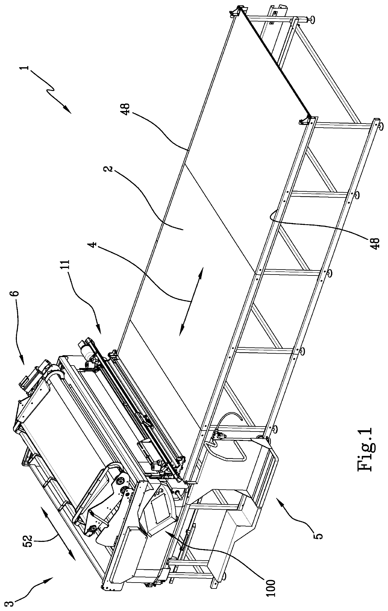
[0060]A machine 1 for spreading fabric on a spreading plane 2 is shown by way of example in FIG. 1.

[0061]The machine comprises a carriage 3 that is movable with rectilinear forward-backward motion along a spreading direction 4 parallel to the spreading plane.

[0062]The carriage typically comprises a footboard 5 (omitted in FIGS. 2-6) solidly constrained thereto for supporting an operator.

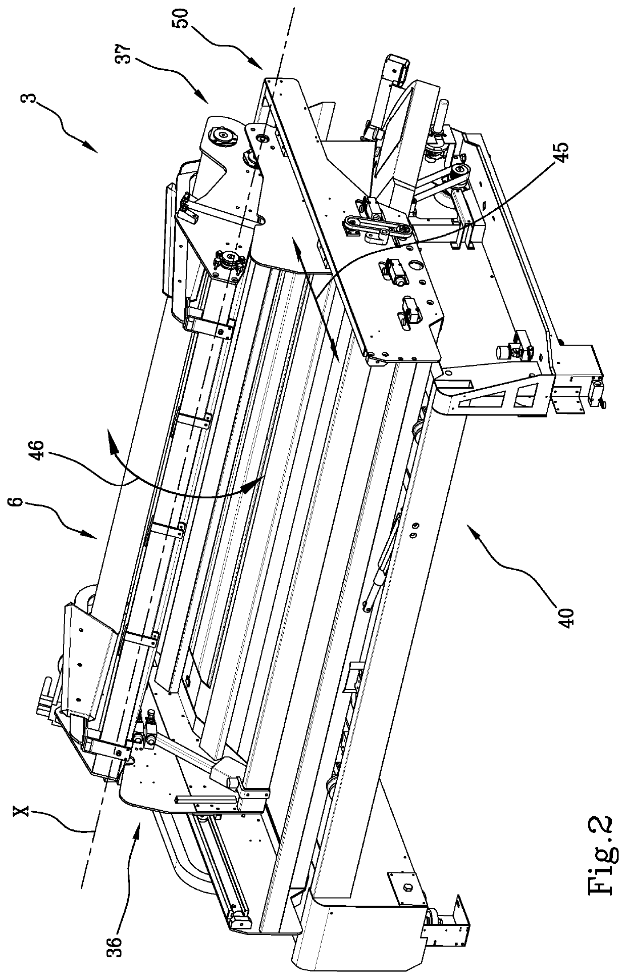
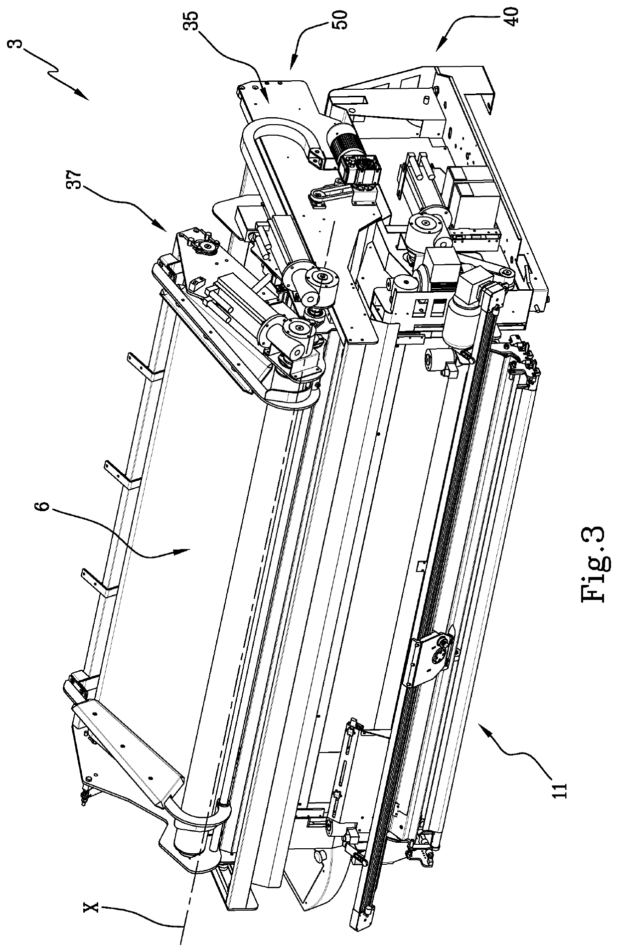
[0063]The carriage comprises an unwinding system 6 comprising a first rotating member 7 for setting a roll of fabric 8 into rotation so as to unwind a strip of fabric 9 (the fabric is schematically shown only in FIGS. 7-11).

[0064]The carriage comprises an inclined chute 10 arranged at a lower level of at least one portion of the first member.

[0065]The carriage comprises a cutting system 11 for cutting the fabric, arranged at a lower end 12 of the chute, downstream of the latter, and comprising a cutting head 13. The cutting head and the movement system thereof for moving it along a direction transver...


PUM

PropertyMeasurementUnit
acute angleaaaaaaaaaa
angleaaaaaaaaaa

Abstract

A machine (1) for spreading fabric on a spreading plane (2) includes a carriage (3) that is movable on the spreading plane, the carriage has an unwinding system (6) for unwinding the fabric; an inclined chute arranged below; a cutting system (11) for cutting the fabric, arranged at a lower end (12) of the chute; and a movement system (35) for moving the unwinding system between a first and a second unwinding operating configuration. In the first configuration, a first end (14) of the unwinding system is vertical to the chute (10) and in the second configuration, the first end (14) is in an advanced position towards the cutting head (13).

Description

[0001]This application is a National Stage Application of PCT / IB2016 / 052657, filed 10 May 2016, which claims benefit of Serial No. MI2015A000675, filed 14 May 2015 in Italy and which applications are incorporated herein by reference. To the extent appropriate, a claim of priority is made to each of the above disclosed applications.BACKGROUND OF THE INVENTION[0002]The object of the present invention is a machine for spreading fabric that is, a machine that is capable of laying out a layer or a number of overlapping layers of fabric on a plane surface, unwinding it from a roll of fabric or from folded fabric.[0003]There are prior-art machines for spreading fabric that comprise a spreading plane and a carriage that is movable with rectilinear forward-backward motion over the spreading plane. A system for unwinding the fabric is mounted on the carriage and comprises a pair of conveyor belts arranged adjacently in a “V” shape so as to define an area for receiving the roll of fabric to be...

Claims


Application Information

Patent Timeline
Patent Type & Authority Patents(United States)
IPC IPC(8): D06H7/02B65H45/103B65H16/10B65H16/02B65H35/06B65H16/04B65H20/06B65H35/00B65H43/00
CPCD06H7/02B65H16/028B65H16/04B65H16/106B65H20/06B65H35/0086B65H35/06B65H43/00B65H45/103B65H2301/51512B65H2404/256B65H2404/692B65H2511/20B65H2511/416B65H2701/174B65H2220/01B65H2220/02B65H2220/11
Inventor GIACHETTI, FRANCO
Owner MORGAN TECNICA
Learn More