Method of welding a component to a shape memory alloy workpiece with provision of an extra cut for compensating the variations of dimension of workpiece and component

a technology of shape memory alloy and component, applied in the direction of prosthesis, manufacturing tools, blood vessels, etc., can solve the problems of inaccurate dimensional tolerance and uncertainty of material removal, and achieve the effect of precise and reliable welding

Active Publication Date: 2012-12-04
CR BARD INC
View PDF108 Cites 23 Cited by
  • Summary
  • Abstract
  • Description
  • Claims
  • Application Information

AI Technical Summary

Benefits of technology

[0010]The present inventor has had the insight that one can use the elastic deformation behaviour of martensitic nickel titanium shape memory alloy to achieve more certainty of location at the welding interface. Nickel titanium shape memory alloy can accommodate remarkably large amounts of strain without adverse effect on the mechanical properties (especially fatigue performance) of the finished stent product. The elastic deformation of nitinol is often referred to as “superelastic” or “pseudo-” elastic deformation, which is considered herein as a form of elastic deformation.
[0012]Typically, in preparing the workpiece for welding, one would provide a slit in the workpiece, remote from the intended welding interface yet close enough to the interface to allow portions of the workpiece that flank the slit to move towards each other, thereby narrowing the slit, to provide all the strain that is needed to achieve the desired welding interface.
[0013]The invention is particularly attractive in the context of a weld interface between the shape memory alloy workpiece and a metallic component that is to be welded to the workpiece, which has a recess in which a portion of the workpiece is received, with the welding interface corresponding to a portion at least at the periphery of the recess. Providing one or more slits within the workpiece, within the periphery of the recess, or in a neck portion of the workpiece crossing the periphery of the recess, can provide the strain that will help to provide a consistent interaction between the workpiece and the metallic component, that will in turn allow precise and reliable welding at the weld interface, and all this without any help from any tooling, jig or other holding fixture to maintain the correct relative positions of the weld surfaces.

Problems solved by technology

This would indicate polishing separately the tantalum markers and the nickel titanium stent, but the chemical polishing process can disturb the accurate dimensional tolerance as achieved when these components are cut with a laser.
One does not know with certainty how much material will have been removed from the intended welding interface by the chemical polishing procedures.

Method used


Image

  • Method of welding a component to a shape memory alloy workpiece with provision of an extra cut for compensating the variations of dimension of workpiece and component
  • Method of welding a component to a shape memory alloy workpiece with provision of an extra cut for compensating the variations of dimension of workpiece and component

Examples


Embodiment Construction

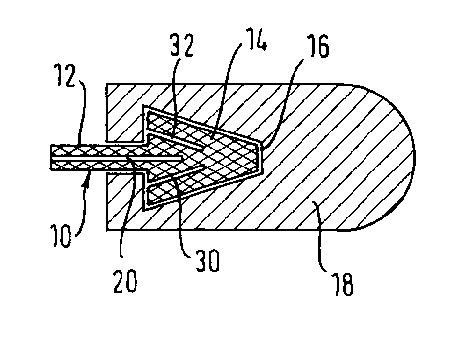
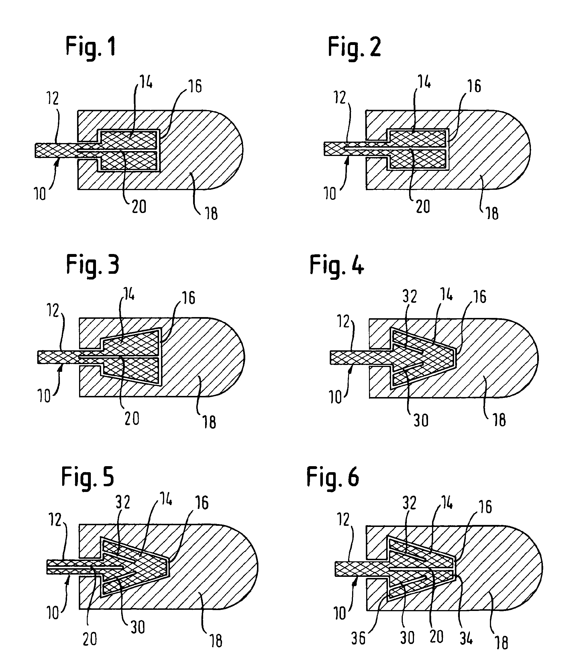
[0016]We refer first to FIG. 1. What is shown is recognisably equivalent to the welding interface in WO 02 / 15820, between a projection at one end of the stent and a “spoon” of tantalum that surrounds the projection and is welded to it. Thus, in FIG. 1, the nickel titanium shape memory alloy stent 10 has at each end (not shown) a plurality of spigots 12, each of which extends like a neck into a head portion 14 that is received in a recess 16 formed in a “spoon”18 of tantalum metal. Typically, each spoon represents ¼ of the circumference of a tube of tantalum having the same radius as the tube of nickel titanium alloy raw material from which the stent matrix is cut by a laser. See WO 02 / 15820 for more information.

[0017]The intended welding interface is at the periphery of the recess 16, the intention being that weld metal from the components themselves should fill the small gap between the periphery of the recess 16 and the periphery of the head portion 14 within it. Nevertheless, it ...


PUM

PropertyMeasurementUnit
lengthaaaaaaaaaa
elastic deformationaaaaaaaaaa
radiopaqueaaaaaaaaaa

Abstract

A method of cutting, polishing and then welding together two metallic components (10, 18), in which the respective components (10, 18) are cut to define respective cut surfaces (14, 16) that are to be polished and fitted together, both to define the relative positions of the two components (10, 18) to be fixed by the welding and to provide facing weld surfaces at which the two components (10, 18) can be welded together. The method is characterized by the steps of i) making at least one extra cut (20), to create at least one zone of elastic deformation that deforms when the cut surfaces (14, 16) are fitted together; ii) polishing the cut surfaces (14, 16) before fitting them together; and iii) designing the dimensions of the cut components (10, 18) so that the zones of elastic deformation compensate for the variations of dimensions caused by the polishing step, thereby retaining the capability of the polished cut surfaces (14, 16, 20) to define said component (10, 18) relative positions during the welding step.

Description

PRIORITY[0001]This application is a U.S. national stage application under 35 USC §371 of International Application No. PCT / EP2007 / 058416, filed Aug. 14, 2007, claiming priority to United Kingdom Patent Application No. 0616729.0, filed Aug. 23, 2006, each of which is incorporated by reference in its entirety into this application.TECHNICAL FIELD[0002]This invention relates to a method of cutting, polishing and then welding together two metallic components, in which the respective components are cut to define respective cut surfaces that are to be polished and fitted together, both to define the relative positions of the two components to be fixed by the welding and provide facing weld surfaces at which the two components can be welded together.BACKGROUND ART[0003]Applicant makes self-expanding stents from nickel titanium shape memory alloy. The material is not particularly radiopaque and so stents made of it are usually provided with one or more radiopaque markers. Tantalum is an att...

Claims


Application Information

Patent Timeline
Patent Type & Authority Patents(United States)
IPC IPC(8): B23K28/00A61F2/06A61F2/82A61F2/91A61F2/915
CPCA61F2/915A61L31/022A61L31/18B23K26/285B23K26/421A61F2/82A61F2/91A61F2002/91591A61F2250/0018A61F2220/005B23K2201/04A61F2250/0098B23K26/282B23K26/60B23K2101/04
Inventor WACK, THILO
Owner CR BARD INC
Why Eureka
Try Eureka