Device for dispersing and dampening impact forces

a technology of impact force and device, which is applied in the direction of protective equipment, protective clothing, weapons, etc., can solve the problems of wearer perspiration, severe internal injuries or deaths, and large volume and weigh

Inactive Publication Date: 2012-12-11
PANOPLY INDS
View PDF7 Cites 21 Cited by
  • Summary
  • Abstract
  • Description
  • Claims
  • Application Information

AI Technical Summary

Problems solved by technology

Unless the impact force is adequately dispersed, the impact force can produce blunt force trauma injuries to the wearer of the ballistic vest, which can result in severe internal injuries or death.
One of the drawbacks with the use of such prior art impact force dispersion and dampening devices is that they tend to be relatively bulky and heavy.
This can be particularly problematic when the wearer of the ballistic vest is deployed in a high temperature environment such as a desert or inside an enclosed motor vehicle.
Because the ballistic vest is often worn during an entire shift or period of deployment in close contact with the wearer's body, the vest can retain significant body heat, causing the wearer to perspire.
Perspiration can weaken the strength and integrity of the ballistic fibers used to form the armor, and thereby diminish the penetration efficiency of the ballistic vest.
Furthermore, the accumulation of perspiration in the vest creates additional weight and makes the vest uncomfortable.
This can motivate a wearer to at least partially remove the ballistic vest, thereby exposing the wearer to harm.

Method used


Image

  • Device for dispersing and dampening impact forces
  • Device for dispersing and dampening impact forces
  • Device for dispersing and dampening impact forces

Examples


example 1

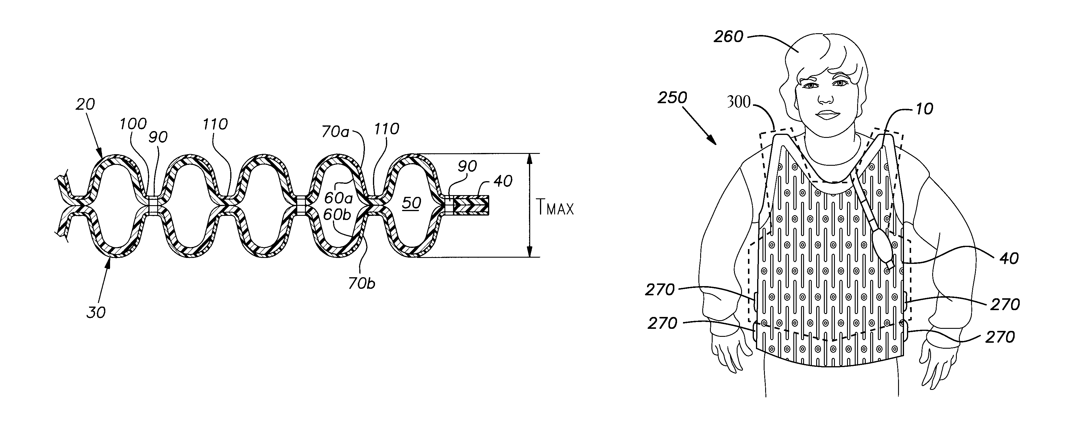
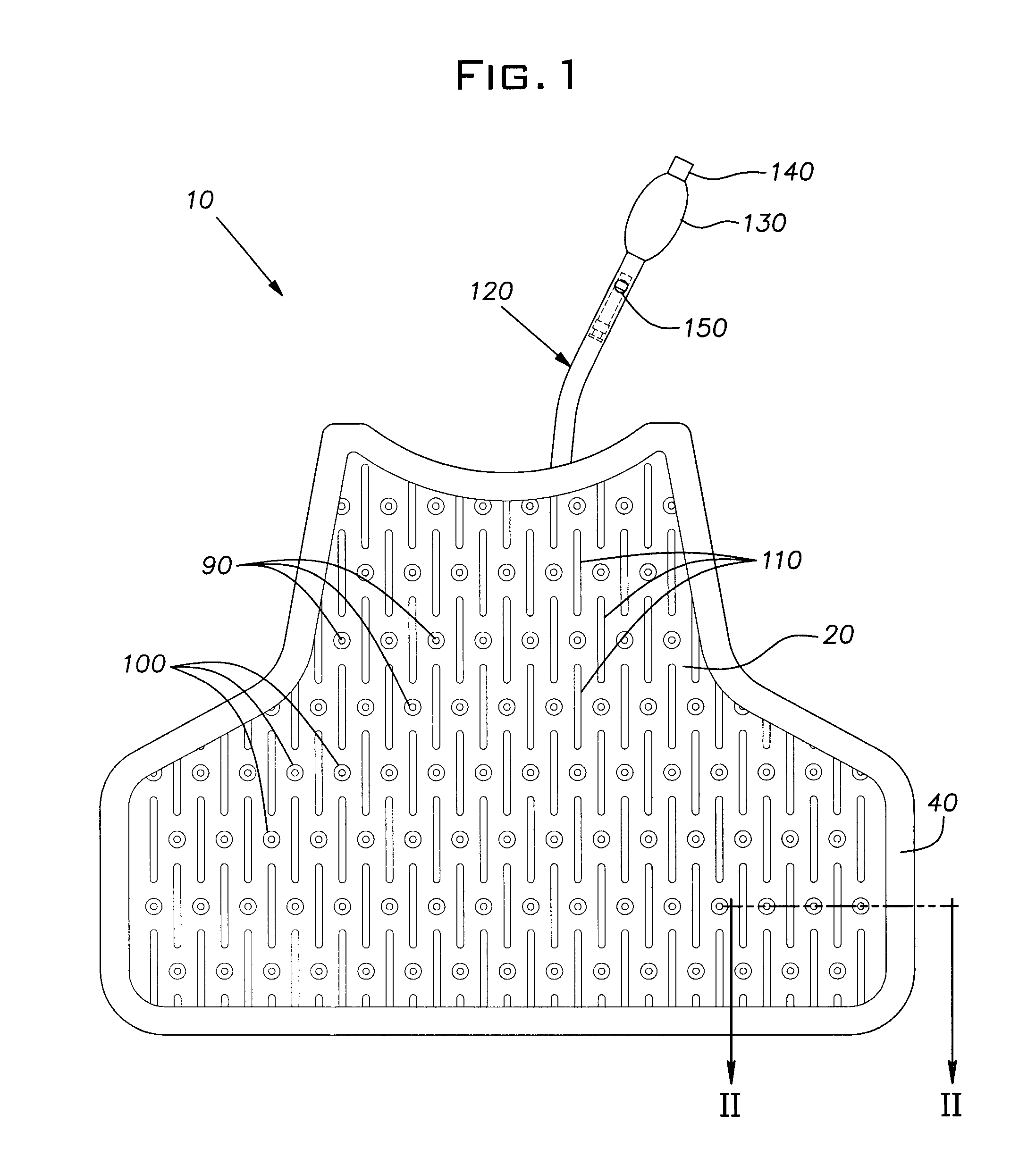
[0080]Two pieces of 200 denier urethane coated nylon procured from Brookwood Laminating of Wauregan, Conn. were cut on the perimeter to a standard size of 18.5″×24″ (˜47 cm×61 cm). Holes were cut through the two layers of fabric, which was placed on a 75 kw Dielectric Fabric Welder with the urethane coated sides of the fabric in contact with each other. The 75 kw welder was pressed down onto the pieces of fabric to form weld seams and the perimeters of the holes to form a device as shown in FIG. 1.

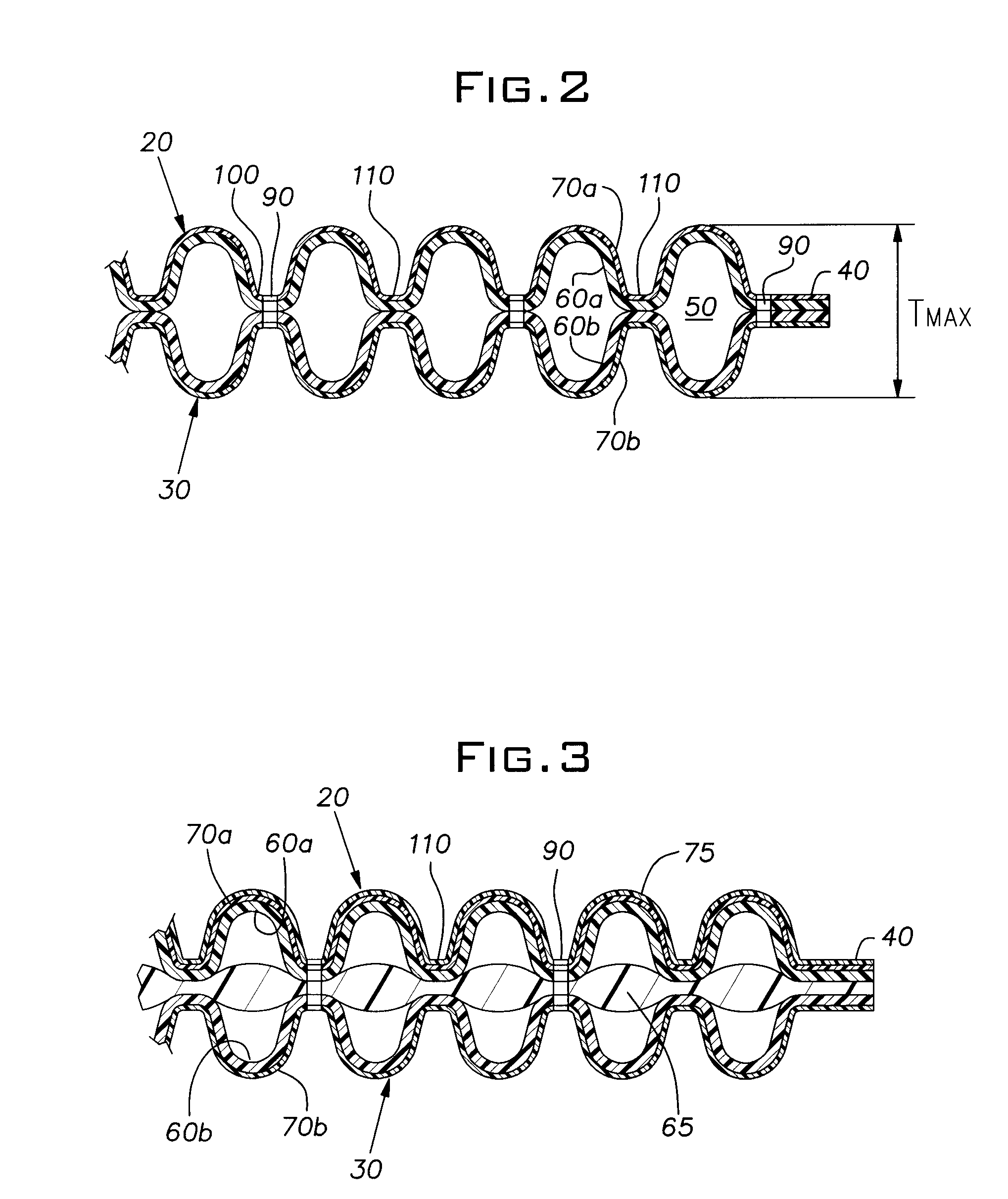
[0081]A SLV-330 valve obtained from Martin-Weston Co. of Largo, Fla. was sealed between the two urethane coated nylon fabric pieces using a 25 kw electric welder. The 75 kw welder was used to form a continuous boundary zone measuring approximately ⅜″ (˜9 mm).

example 2

[0082]The device manufactured as described in Example 1 was tested for impact force dispersion and dampening efficiency using the test method set forth in NIJ 0101.04. A conventional XT-2 Type II ballistic vest obtained from American Body Armor of Jacksonville, Fla., USA was used. Table 1 below provides the results of the testing. For the “Example 1” data, the device according to the invention as manufactured in Example 1 was placed between the conventional XT2-2 ballistic vest and the backing material. For the “Control” data, the conventional XT2-2 ballistic vest alone.

[0083]

TABLE 1PerformanceImpact ForceMaximumDispersingTest VariablesDepth ofandCaliber ofHits at 0°DeformationDampeningTestTestAngle ofin BackingDeviceRoundAmmunitionIncidenceMaterialControl1.38117.8 mm 2.3572 33 mmExample 11.3815.8 mm2.35719.6 mm

[0084]The performance results shown in Table 1 demonstrate that the device according to the invention is very efficient at dispersing and dampening impact forces transferred ...


PUM

PropertyMeasurementUnit
pressureaaaaaaaaaa
pressuresaaaaaaaaaa
widthaaaaaaaaaa

Abstract

A device for dispersing and dampening impact forces that includes a first sheet structure and a second sheet structure that are joined together at a boundary zone. The boundary zone joins the first sheet structure and the second sheet structure together to define at least one gas-tight chamber having two sides. A gas is contained within the gas-tight chamber at a pressure within a predetermined range of acceptable pressures for dispersing impact forces translated against one side of the device such that a blunt force trauma producing impact force is not transferred through the device to a wearer's body disposed proximal to the other side of the device.

Description

BACKGROUND OF INVENTION[0001]1. Field of Invention[0002]The present invention relates to a method and a device for dispersing and dampening impact forces.[0003]2. Description of Related Art[0004]There are a many applications where it is highly desirable, if not absolutely vital, to effectively disperse and dampen impact forces directed toward a person or an object. One such application is in the field of body armor.[0005]Body armor, which may include a ballistic vest (also known as a “bullet-proof” vest) alone or in combination with other protective clothing such as, for example, a helmet, ballistic shoulder armor and / or ballistic leg armor, is worn to protect a wearer's body from being pierced by gun-fired projectiles and explosive fragments. The most commonly used body armor is a ballistic vest, which protects the wearer's torso and thus the wearer's vital organs from penetration injuries.[0006]In the past, ballistic vests were formed using steel plates and / or other rigid, heavy m...

Claims


Application Information

Patent Timeline
Patent Type & Authority Patents(United States)
IPC IPC(8): F41H1/02
CPCF41H1/02F41H5/0478
Inventor FELDMAN, VLADIMIRMIROSHNIK, LEONIDGUNZBURG, ELI
Owner PANOPLY INDS
Why Eureka
Try Eureka