
Cushion bladder with middle layer having gaps and various positioned interior welds

a technology of cushioning bladder and middle layer, which is applied in the field of cushioning devices, can solve the problems of affecting well-being, /or immediate air loss, and bed sores and other complications

Active Publication Date: 2012-12-18
STRYKER CORP
View PDF18 Cites 24 Cited by
  • Summary
  • Abstract
  • Description
  • Claims
  • Application Information

AI Technical Summary

Benefits of technology

The cushioning device has three layers of material sealed together at the edges to form a right side, a head end, a left side, and a foot end. A middle material is positioned between the first and second materials and has gaps between its top and bottom sides. The first and second materials are sealed to the middle material's top and bottom surfaces, respectively, to form interior welds that do not overlap. The technical effect of this design is a more stable and reliable cushioning device that provides better shock absorption and durability.

Problems solved by technology

It is well known that interface pressures can significantly affect the well-being of immobile patients in that higher interface pressures can reduce local blood circulation, tending to cause bed sores and other complications.
There is a problem when a handle is used in the prior art cushion design.
Leakage at the button welds and edges is undesirable because it results in bottoming, described above, and / or immediate air losses.
Once the air is directed to the edges, the edges increase in size and form a “hot-dog roll” structure about the patient and then the edges may burst.
Obviously, leaking, bottoming and immediate air losse are undesirable effects when a person re-positions a prior art cushion.

Method used


Image

  • Cushion bladder with middle layer having gaps and various positioned interior welds
  • Cushion bladder with middle layer having gaps and various positioned interior welds
  • Cushion bladder with middle layer having gaps and various positioned interior welds

Examples


Embodiment Construction

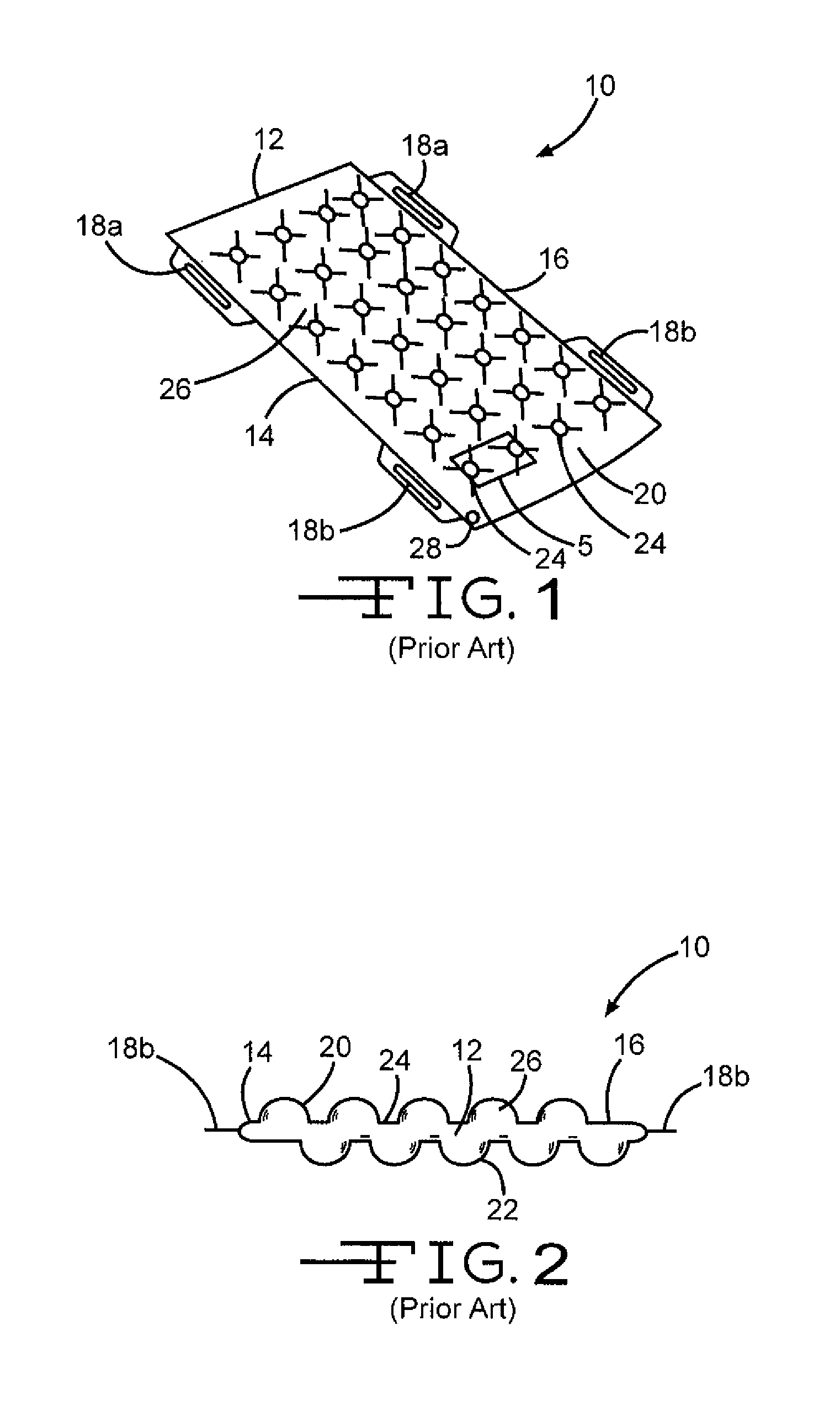
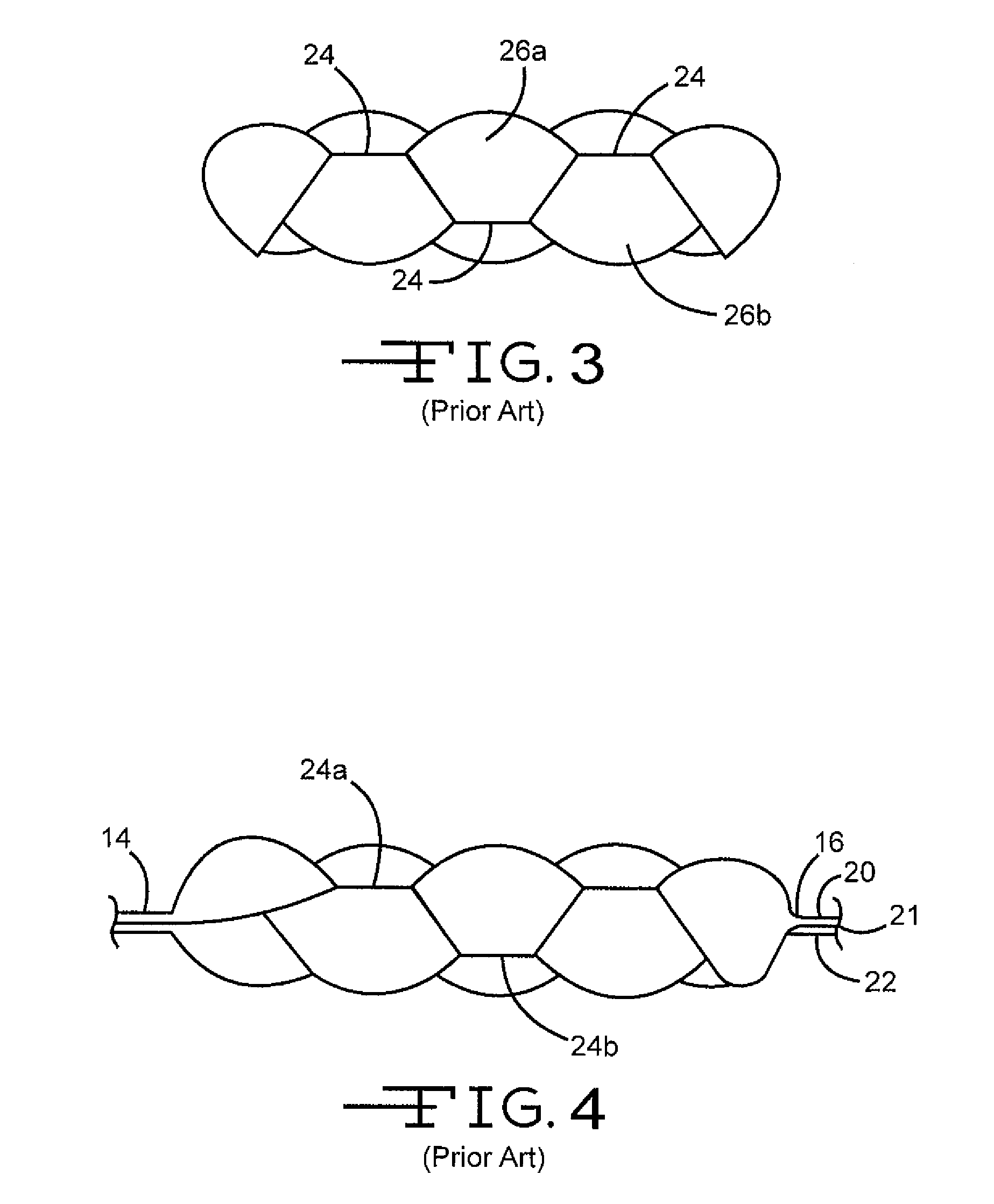
[0023]The above-identified prior art cushion structure and the claimed invention are similar in some ways, and different in others.

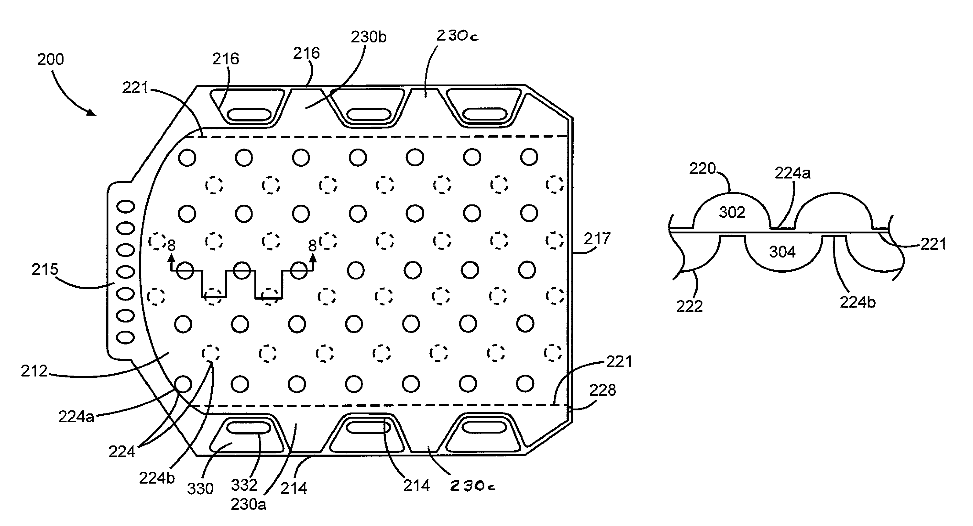
[0024]The claimed invention is a cushioning device 200 as shown in FIGS. 7-10. The cushioning device 200 includes a cushioning section 212, which supports the user and provides pressure relief to the user so that the development of pressure ulcers is prevented or retarded. The cushioning section 212 is an inflatable bladder having a first surface 220 and an opposing second surface 222 (see FIG. 8) joined at a first (right) side 214, a first (head) end 215, a second (left) side 216 and / or a second (foot) end 217.

[0025]The first surface 220 and the opposing second surface 222 can each be a three-ply puncture-resistant vinyl film or other suitable air impervious flexible material, a two-ply air impervious flexible material, or an air impervious flexible material. The first surface 220 and the opposing second surface 222 can also be two distinct pieces of ma...


PUM


Abstract

A cushioning device has a first material and an opposing second material that are sealed together at the peripheral edges to form a first (right) side, a first (head) end, a second (left) side, and a second (foot) end. Positioned between the first material and the second material is a middle material. The middle material has a top side, a bottom side, a first gap between the first side and the middle material and a second gap between the second side and the middle material. In addition, the first material is sealed to the middle material's top side at a first set of locations to form a first set of interior welds. The second surface is sealed to the middle material's bottom surface at a second set of locations to form a second set of interior welds. The first set of interior welds on the middle material's top surface and the second set of interior welds on the middle material's bottom surface are not superimposed on each other or overlap each other.

Description

FIELD OF THE INVENTION[0001]The present invention relates to a cushioning device, such as an overlay for a mattress.BACKGROUND OF THE INVENTION[0002]Therapeutic supports for bedridden patients have been well known for many years. Such therapeutic supports include inflatable mattresses and cushions, as well as a variety of foam mattresses and cushions. Most therapeutic mattresses and cushions are designed to reduce “interface pressures,” which are the pressures encountered between the mattress and the skin of a patient lying on the mattress. It is well known that interface pressures can significantly affect the well-being of immobile patients in that higher interface pressures can reduce local blood circulation, tending to cause bed sores and other complications. With inflatable mattresses, such interface pressures depend (in part) on the air pressure within the inflatable support cushions. Most inflatable therapeutic mattresses are designed to maintain a desired air volume within th...

Claims


Application Information

Patent Timeline
Patent Type & Authority Patents(United States)
IPC IPC(8): A47C27/00
CPCA61G7/05769A47C27/081A47C31/08
Inventor FLICK, ROLAND E.ENDRESS, SCOTTMAZZU, EDWARD
Owner STRYKER CORP
Learn More