

Method for attaching a hand held electronic device to a soft object and coupling therefor
a technology of electronic devices and soft objects, which is applied in the direction of curtain suspension devices, electric apparatus casings/cabinets/drawers, instruments, etc., can solve the problem of not having a convenient way to support hand held electronic devices
- Summary
- Abstract
- Description
- Claims
- Application Information
AI Technical Summary
Problems solved by technology
Method used
Image

Examples
second embodiment
[0055]FIG. 14 is a side elevation view of coupling 20. In this embodiment, first connector 26 is rotatable with respect to second connector 28, so that when coupling 20 attaches hand held electronic device 500 to soft object 600, hand held electronic device 500 can be rotated to a desired angular position (refer to FIGS. 19 and 20). In the shown embodiment, the rotation is effected by splitting coupling 20 in half and providing an axle 34 which rotationally connects first connector 26 and second connector 28.
[0056]FIGS. 15-18 show second connector 28 at different rotational positions with respect to first connector 26 (refer to FIG. 14). As shown, second connector 28 has been rotated 90° between views. It may be appreciated that other amounts of angular rotation could also be performed (e.g. 30°, 60°, 45°, 37°, etc.).
[0057]FIG. 19 is a side elevation view of the rotational embodiment of coupling 20 attaching hand held electronic device 500 to soft object 600. FIG. 20 is a side eleva...
third embodiment
[0060]FIG. 22 is a perspective view of coupling 20. In this embodiment first connector 26 of coupling 20 is removably attachable to cover 510 of hand held electronic device 500 (rather than being directly attachable to hand held electronic device 500 as in the previous embodiments). First connector 26 includes a planar member 27 which is removably connectable to second connector 28 by a connective member 25 which is shaped and dimensioned to pass through aperture 516 in removable cove 510. Connective member 25 can be passed through aperture 516 in removable cover 510 so that the planar member 27 is disposed between inside surface 514 of removable cover 510 and hand held electronic device 500 (refer also to FIG. 24 and the associated discussion).
[0061]FIG. 23 is a perspective view of the third embodiment coupling 20 attached to hand held electronic device 500 and cover 510, and FIG. 24 is a cross sectional view along the line 24-24 of FIG. 23. Coupling 20 is attached to cover 510 pri...
fourth embodiment
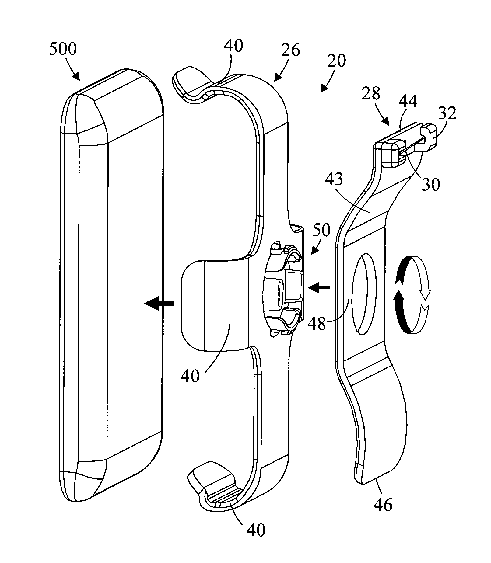
[0064]FIGS. 28-31 are perspective, reverse perspective, exploded perspective, and side Elevation views respectively of a fourth embodiment coupling 20 attached to hand held electronic device 500. In this embodiment, first connector 26 includes a holder for accepting and holding hand held electronic device 500. In the shown embodiment the holder has four arms 40 which releasibly clamp around hand held electronic device 500. Second connector 28 includes a flange 43 having a first end 44, an opposite second end 46, and a central portion 48. In the shown embodiment, first 44 and second 46 ends of flange 43 are curved away from first connector 26. Pin 30 and catch mechanism 32 are disposed at first end 44 of flange 43. First connector 26 and second connector 28 (i.e. flange 43) are rotationally connected by a rotational device 50 so that the flange 43 rotates about central portion 48 with respect to first connector 26. When second connector 28 is attached to soft object 600 (at 47, refer...
PUM
 Abstract
Description
Claims
Application Information