Electric shock resistant L.E.D. based light

a technology of led light and electric shock resistance, which is applied in the direction of lighting safety devices, semiconductor devices of light sources, lighting and heating apparatus, etc., can solve the problems of generating a charge in the heat sink, exposing the exposed metal of the based fluorescent tube replacement light, and presenting a shock hazard, etc., and achieves the effect of sufficient thermal managemen

Active Publication Date: 2013-01-29
ILUMISYS
View PDF1049 Cites 192 Cited by
  • Summary
  • Abstract
  • Description
  • Claims
  • Application Information

AI Technical Summary

Benefits of technology

[0005]The present invention eliminates the shock hazard potential present in LED-based lights of the type having exposed metal heat sinks while still providing sufficient thermal management of heat produced by the LEDs. In general, a shock-resistant replacement light for a conventional fluorescent tube light usable in a conventional fluorescent fixture includes a generally tubular body of high-dielectric material forming the outer surface of the light over substantially its entire length. A circuit board structure is disposed within the body and thermally joined thereto while being electrically insulated therefrom. A pair of end caps carrying bi-pin connectors is disposed on the opposite ends of the body. An array of high-powered LEDs is arranged longitudinally along the circuit board and thermally bonded thereto, the number and spacing of the LEDs being such as to uniformly and fully occupy the space between the end caps. The body is translucent at least in part so as to permit the transmission of light from the LEDs through the body. At least some of the connectors on the end caps are electrically connected to the LEDs.

Problems solved by technology

The inventors have discovered that the LED-based fluorescent tube replacement lights with exposed metal heat sinks as described above can present a shock hazard during installation.
Because the heat sink in the LED-based light is positioned closely to the circuit board, the high-frequency starting voltage can cause parasitic capacitive coupling between the circuit board and the heat sink, thereby producing a charge in the heat sink.
A person installing the LED-based light is often touching the metal heat sink, providing a ground for the charge to pass through and resulting in a significant electrical shock to the person.

Method used


Image

  • Electric shock resistant L.E.D. based light
  • Electric shock resistant L.E.D. based light
  • Electric shock resistant L.E.D. based light

Examples


Embodiment Construction

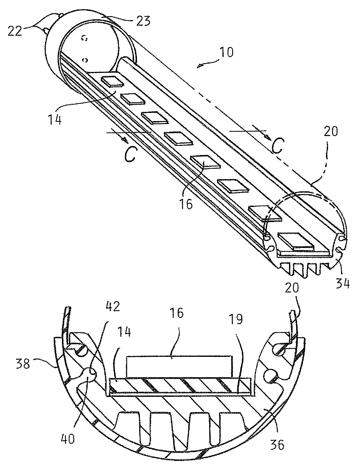
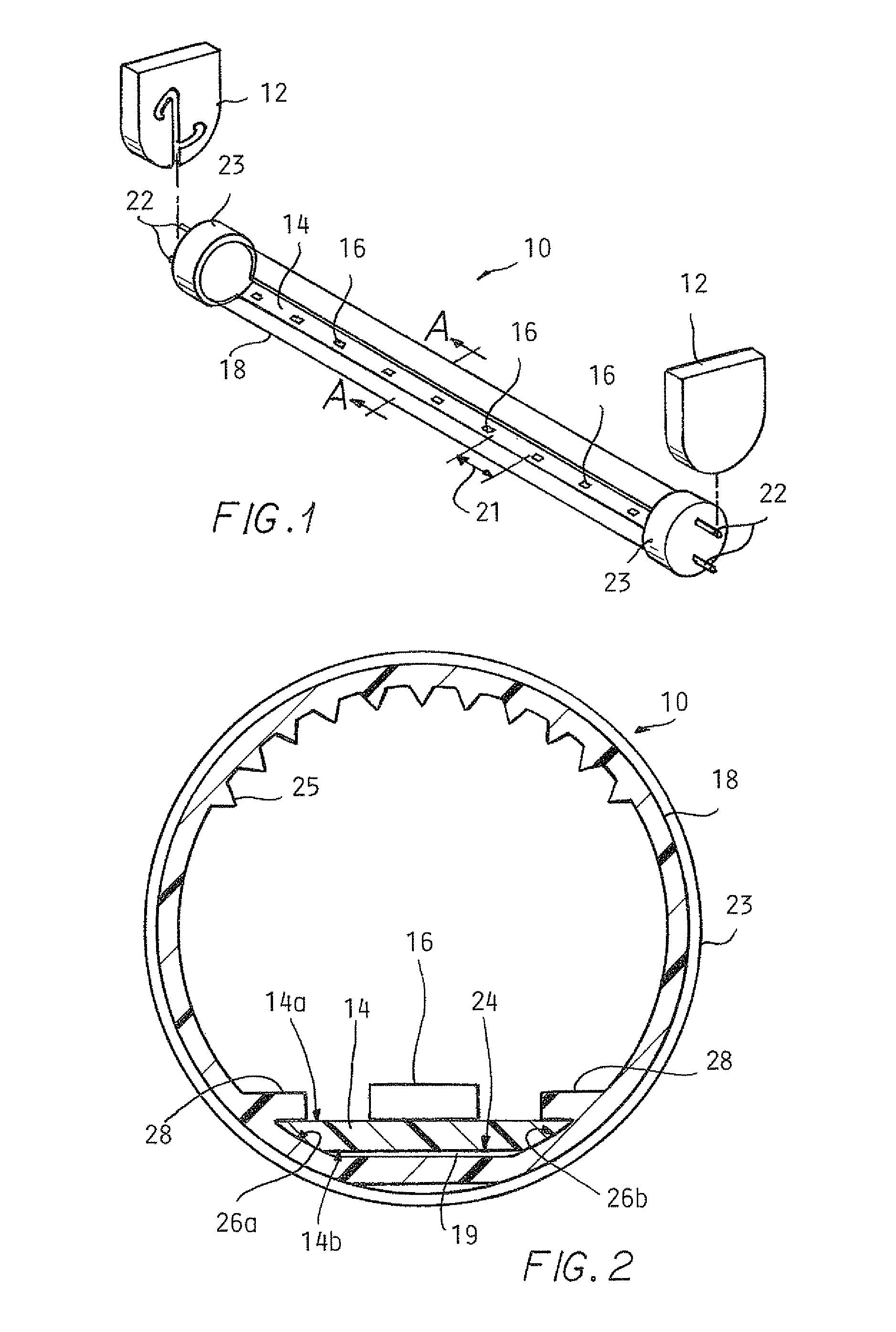
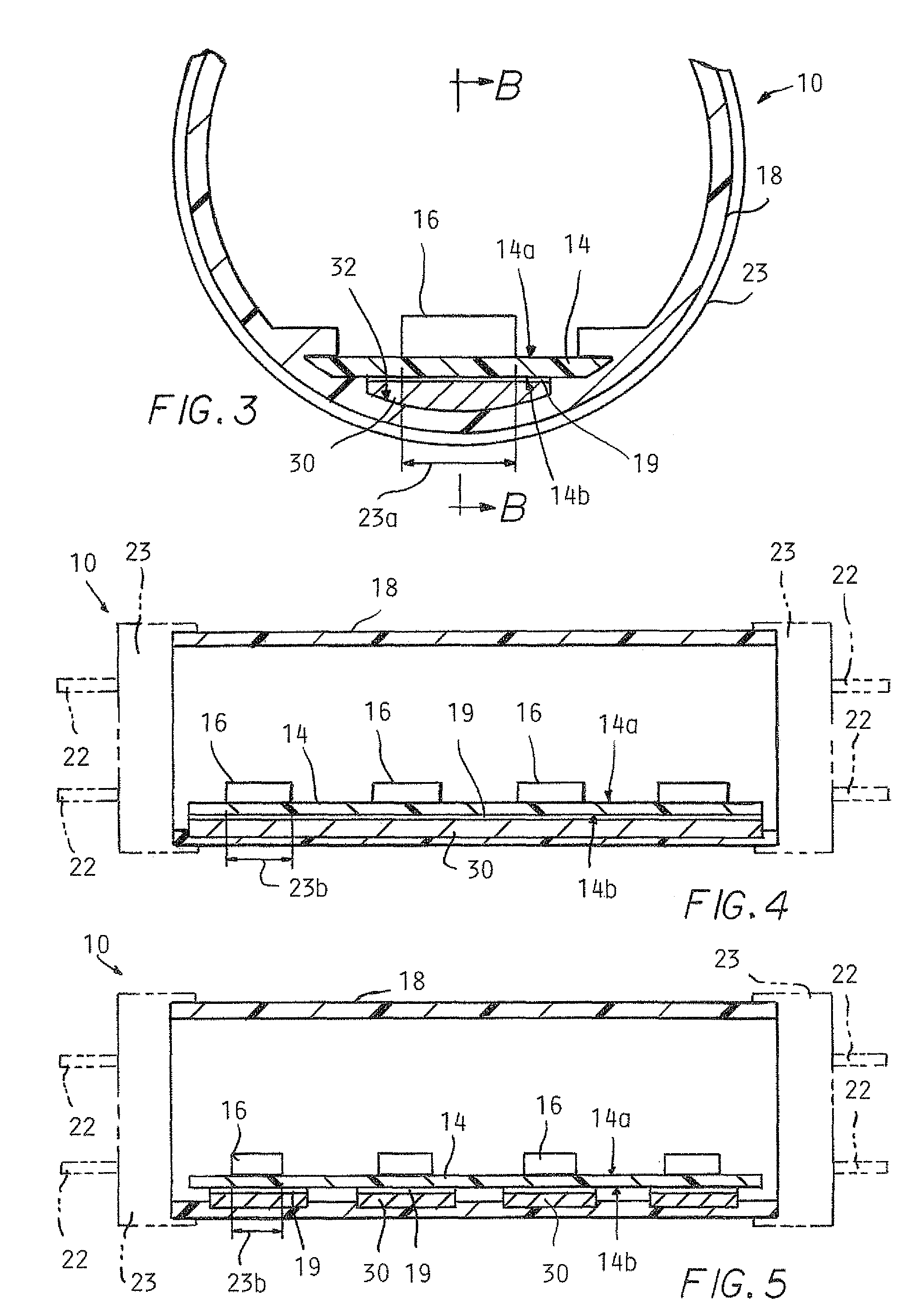
[0020]FIGS. 1-10 illustrate LED-based replacement lights 10 according to the present invention for replacing a conventional fluorescent light bulb in a fluorescent fixture 12. The lights 10 each include a circuit board 14, multiple LEDs 16, a tubular housing at least partially defined by a high-dielectric translucent portion, and bi-pin electrical connectors 22 affixed to plastic end caps 23.

[0021]FIGS. 1 and 2 show an illustrative embodiment of the present invention in which the tubular housing consists of a tube 18. The circuit board 14 has a LED-mounting side 14a and a primary heat transferring side 14b opposite the LED-mounting side 14a. The circuit board 14 may be made in one piece or in longitudinal sections joined by electrical bridge connectors. The circuit board 14 and the tube 18 are in thermally conductive relation with the circuit board 14 attached to the tube 18 using highly thermally conductive adhesive transfer tape 19. The circuit board 14 can alternatively be positi...


PUM


Abstract

A LED-based replacement light for a fluorescent socket is constructed such that an entirety of a radially outer portion of a tubular housing at least partially defined by a high-dielectric light transmitting portion is formed of a high-dielectric material. Forming a radially outer portion of the tubular housing of a high-dielectric material prevents a person handling the light from being shocked as a result of capacitive coupling occurring when the LED-based replacement light is installed one end at a time. A circuit board is in thermally conductive relation with the tubular housing, allowing for conduction of heat generated by the LEDs from a side of circuit board opposite the LEDs to the tubular housing for dissipation to the ambient environment.

Description

TECHNICAL FIELD[0001]The present invention relates to a light emitting diode (LED) based light for replacing a conventional fluorescent light in a fluorescent light fixture.BACKGROUND[0002]Fluorescent tube lights are widely used in a variety of locations, such as schools and office buildings. Although conventional fluorescent bulbs have certain advantages over, for example, incandescent lights, they also pose certain disadvantages including, inter alia, disposal problems due to the presence of toxic materials within the glass tube.[0003]LED-based tube lights which can be used as one-for-one replacements for fluorescent tube lights having appeared in recent years. One such LED-based fluorescent replacement light includes LEDs mounted on an elongated circuit board in a semi-cylindrical metal housing which also serves as a heat sink for the LEDs. A U-shaped lens snaps onto the heat sink to cover the LEDs and disperse light from them.BRIEF SUMMARY[0004]The inventors have discovered that...

Claims


Application Information

Patent Timeline
Patent Type & Authority Patents(United States)
IPC IPC(8): F21V7/20F21V29/00F21S4/00F21V29/505
CPCF21K9/17F21V23/06F21V29/70F21V29/20F21Y2101/02F21Y2103/003F21V29/89F21V29/506F21V29/75F21V29/763F21V25/00F21K9/27F21Y2103/10F21Y2115/10F21K9/69F21S4/00
Inventor IVEY, JOHNSIEMIET, DENNIS
Owner ILUMISYS
Why Eureka
Try Eureka