Securing mechanism for shackle

a technology of shackles and fixing mechanisms, which is applied in the direction of hose connections, screws, rod connections, etc., can solve the problem of thread over tightening

Active Publication Date: 2013-02-26
CROSBY GROUP
View PDF44 Cites 18 Cited by
  • Summary
  • Abstract
  • Description
  • Claims
  • Application Information

AI Technical Summary

Problems solved by technology

In either type, there is a possibility of over tightening the threads.

Method used


Image

  • Securing mechanism for shackle
  • Securing mechanism for shackle
  • Securing mechanism for shackle

Examples


Embodiment Construction

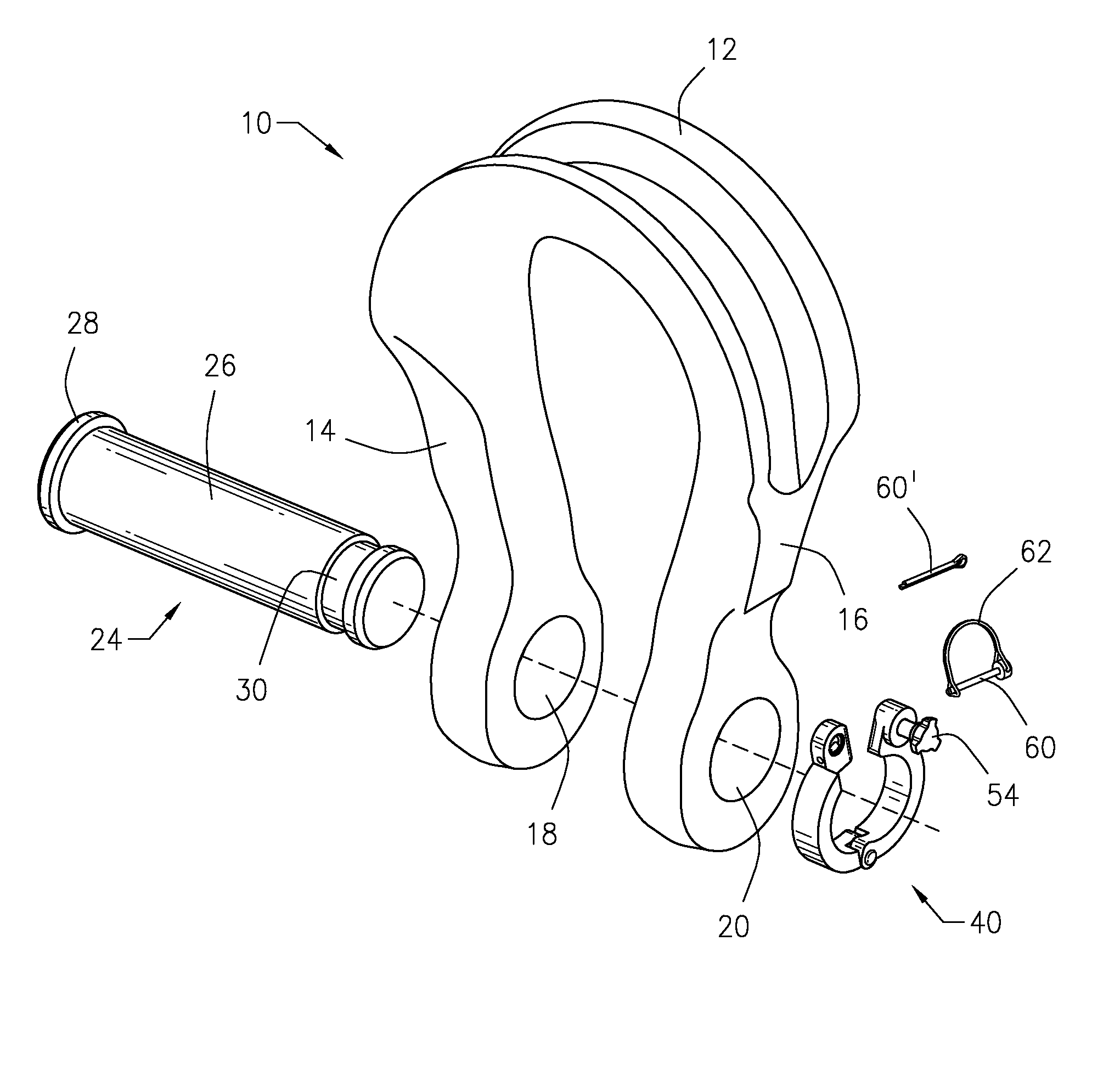
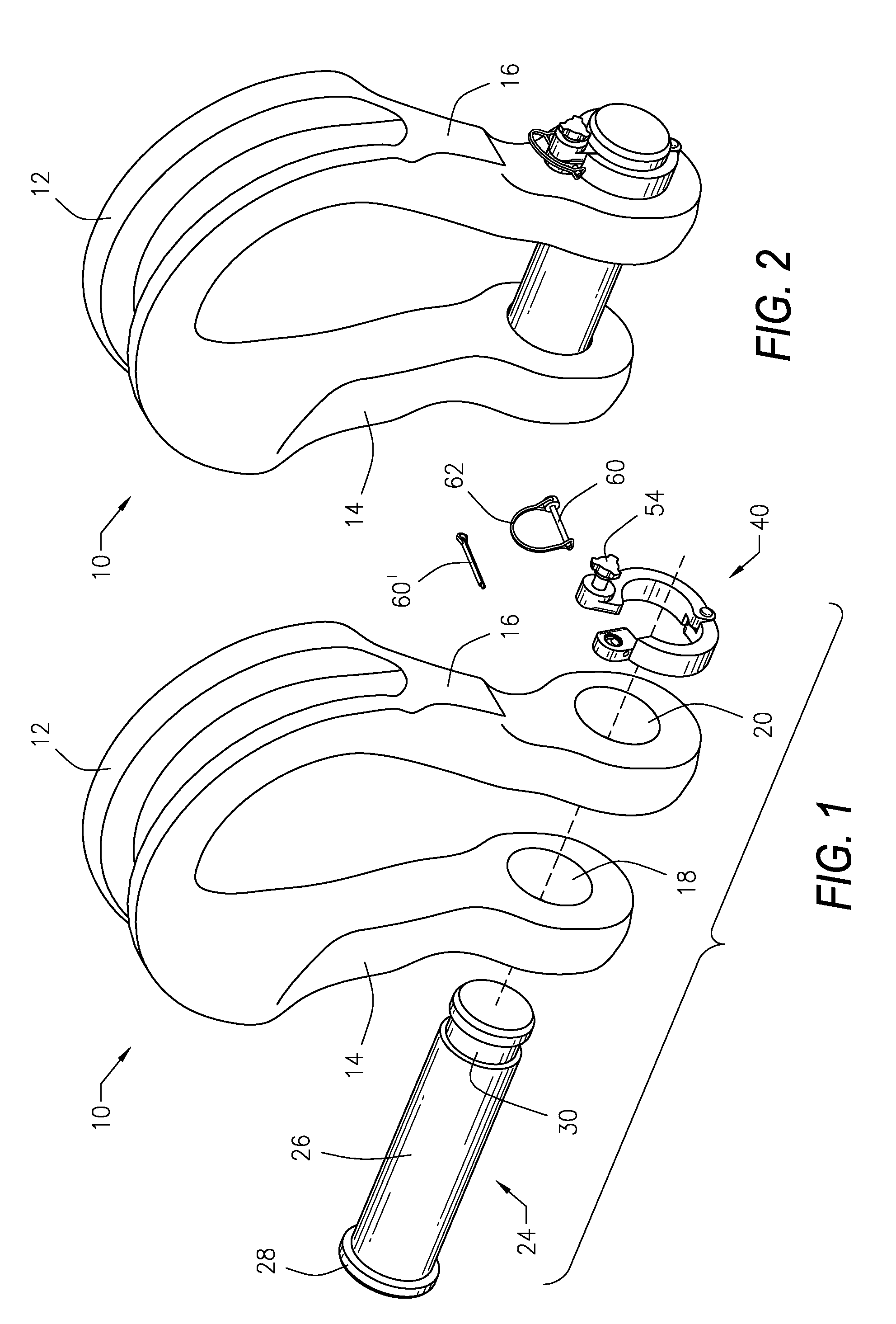
[0025]Referring to the drawings in detail, FIG. 1 illustrates an exploded view and FIG. 2 illustrates a fully assembled view of a shackle 10 having a body 12 and a pair of opposed clevis ears or legs 14 and 16 extending from the body 12. It will be appreciated that the shackle body and the ears or legs may take various configurations within the spirit and scope of the present invention.

[0026]Each of the legs 14 and 16 has an opening 18 and 20, respectively, to form a pair of opposed aligned openings 18 and 20.

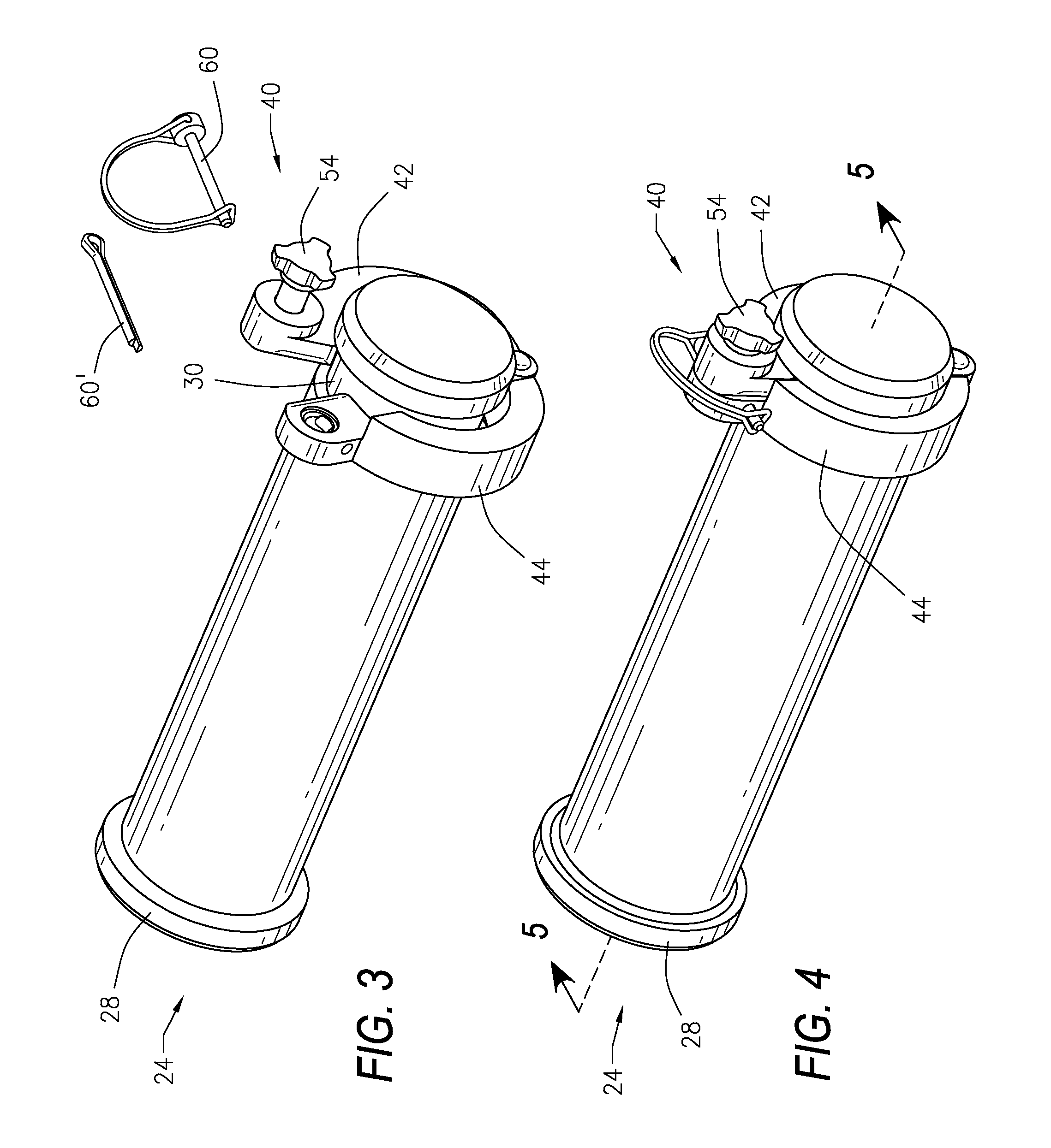
[0027]A clevis pin or shackle bolt 24 has a cylindrical body having an external diameter slightly less than the diameter of the opposed leg openings 18 and 20. Accordingly, the shackle bolt 24 may be received in and through the openings 18 and 20. The shackle bolt 24 has an enlarged head 28 larger than the diameter of the cylindrical body at one end.

[0028]The shackle 10, the shackle bolt 24 and other elements may be fabricated from carbon steel or alloy steel, although other ma...


PUM

PropertyMeasurementUnit
diameteraaaaaaaaaa
circumferenceaaaaaaaaaa
widthaaaaaaaaaa

Abstract

A securing mechanism for a shackle having a pair of opposed legs with an opening at one end of each of the pair of opposed legs to form a pair of opposed openings. The securing mechanism includes a shackle bolt having a head at one end and a circumferential groove near an opposed end wherein the shackle bolt is received through the pair of opposed openings in the shackle. A two piece hinged clamp assembly is received in the circumferential groove in order to retain the shackle bolt in the shackle. A retainer pin is received in an opening in the two piece clamp assembly to hold the two piece clamp assembly in a closed position. A retainer clip surrounds the retainer pin. A lock pin through the two piece clamp assembly retains the retainer pin in the two piece clamp.

Description

BACKGROUND OF THE INVENTION[0001]1. Field of the Invention[0002]The present invention is directed to a securing apparatus for a shackle and to a method for securing a shackle bolt to a shackle. In particular, the present invention is directed to an apparatus and a method of securing a shackle bolt to a shackle utilizing a hinged split nut providing both easy installation and removal of the shackle bolt.[0003]2. Description of the Related Art[0004]A shackle is one type of known device used to join sling cables or ropes together or used to connect a cable or rope to a load. Among the many applications for shackles are tie down, towing, suspension or lifting applications.[0005]Presently, the securing mechanism utilized is typically either a screw pin type, which is received in a threaded opening, or a bolt type anchor along with a threaded nut and a cotter pin. In order to disassemble, the cotter pin must be removed from the shackle bolt and then the nut must be unthreaded from the sha...

Claims


Application Information

Patent Timeline
Patent Type & Authority Patents(United States)
IPC IPC(8): F16G11/09
CPCF16G15/06F16B45/00F16B21/16Y10T24/1486Y10T24/1459Y10T24/1471Y10T24/1457Y10T29/4995Y10T24/14Y10T24/3956Y10T24/1492
Inventor BOECKMAN, PAUL A.BEALL, ROGER E.WHITEHEAD, CHRIS
Owner CROSBY GROUP
Why Eureka
Try Eureka