Dirt separator device with level control

a technology of level control and separator, which is applied in the direction of water supply installation, washing apparatus, functional valve types, etc., can solve the problems of no longer any cleaning function in the corresponding section of the cleaning apparatus, increase equipment expenditure, and reduce the level of cleaning liquid in the associated supply tank, so as to achieve the effect of minimal outlay on a sensor system or other apparatus, and high degree of functional reliability

Active Publication Date: 2013-03-19
MEIKO MASCHENBAU
View PDF9 Cites 0 Cited by
  • Summary
  • Abstract
  • Description
  • Claims
  • Application Information

AI Technical Summary

Benefits of technology

[0012]It is therefore an object of the present invention to provide an apparatus for level control in a fluid tank, which apparatus can be used, in particular, in a cleaning apparatus with a treatment apparatus, and which apparatus at least largely avoids the disadvantages of the above-described prior art. In particular, a high degree of functional reliability as regards level control and, at the same time, minimal outlay on a sensor system or other apparatuses should be ensured.

Problems solved by technology

However, this reduces the level of cleaning liquid in the associated supply tank.
However, this means increased outlay on equipment.
However, if the quantity of water flowing in is not sufficient for operation- or method-related reasons, a circulation pump for cleaning and / or the circuit through the treatment apparatus, for example, has to be disconnected.
This results in the disadvantage that there is no longer any cleaning function in the corresponding section of the cleaning apparatus in this case, or that the treatment of cleaning liquid is put out of operation.
A further disadvantage of the described procedures is that an increased quantity of cleaning liquid is consumed.
For example, continuous refilling of water to maintain the function of the cleaning apparatus can be associated with increased water consumption.
Overall, the apparatuses known from the prior art therefore have the disadvantage that a considerable amount of additional outlay on a sensor system and additional apparatuses is required in order to control the liquid level in the supply tank, if any such control is provided at all, and this considerably increases the costs and the technical outlay on the cleaning apparatus overall.
This also results in an increased susceptibility of the cleaning apparatuses to faults.

Method used


Image

  • Dirt separator device with level control
  • Dirt separator device with level control
  • Dirt separator device with level control

Examples


Embodiment Construction

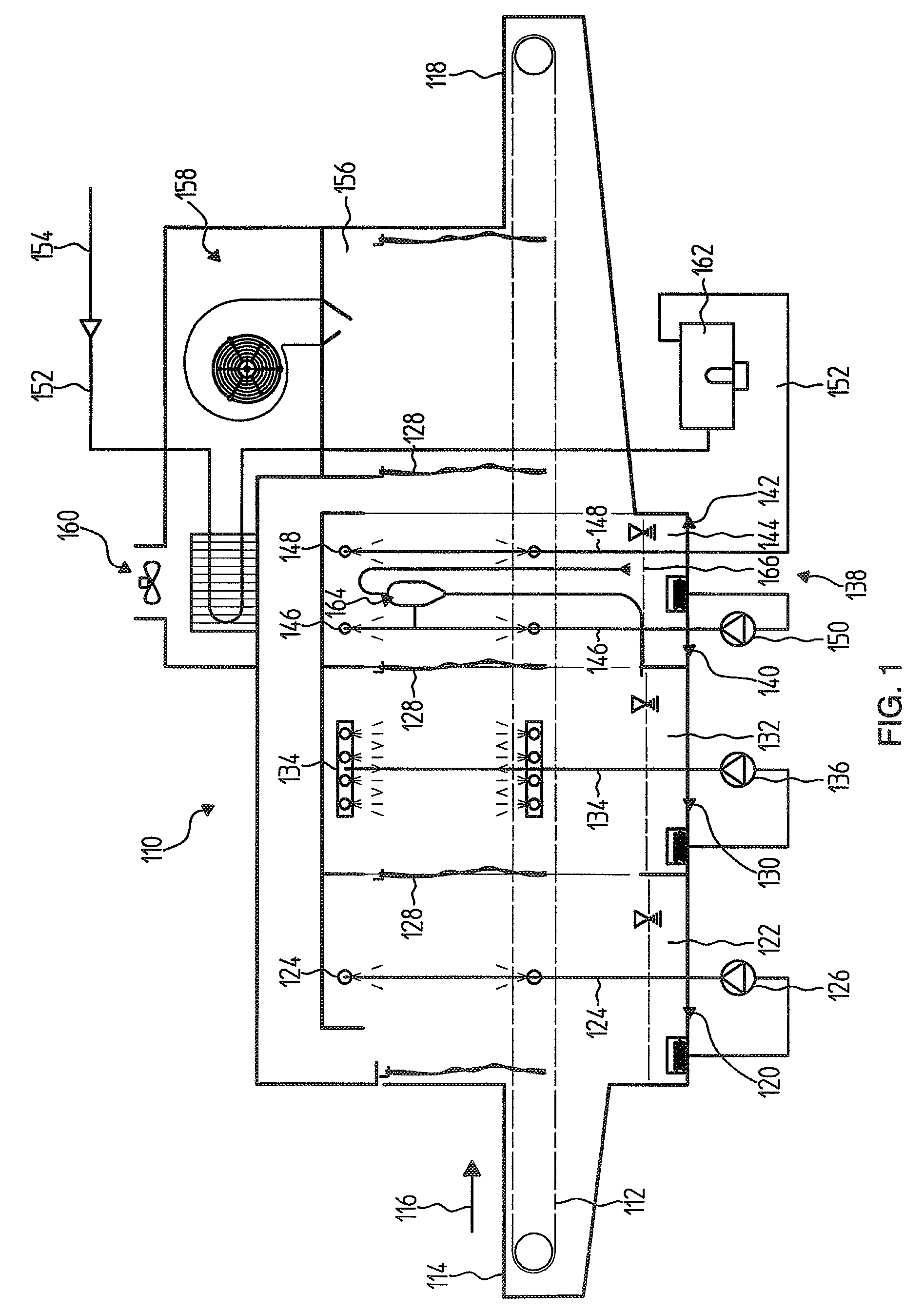
[0040]FIG. 1 illustrates one possible exemplary embodiment of a cleaning apparatus 110 according to the invention. In this exemplary embodiment, the cleaning apparatus 110 is configured as a conveyor-type dishwasher and has a transportation apparatus 112 for transporting the washware. The washware is placed on the transportation apparatus 112 at a charge point 114, for example directly or using racks, and is transported through the cleaning apparatus 110 in a transportation direction 116, in order to then be removed again, in the cleaned state, at a discharge point 118 at the outflow end of the cleaning apparatus 110.

[0041]In the illustrated exemplary embodiment, the cleaning apparatus 110 has a plurality of cleaning zones through which the washware is passed in succession. Therefore, a pre-wash zone 120 is provided and has a pre-wash tank 122 and a pre-wash system 124 which is fed from the pre-wash tank 122 by means of a pre-wash pump 126.

[0042]A main-wash zone 130 with a main-wash...


PUM


Abstract

An apparatus for level control in a fluid tank is provided, wherein the fluid tank is designed to accommodate a supply of a fluid. The apparatus includes at least one conveying line through which the fluid can flow and which has at least one control opening which is hydraulically connected to the fluid tank. The control opening is designed to at least largely prevent fluid flowing out of the conveying line and into the fluid tank when at least one minimum level in the fluid tank is exceeded, and the control opening is further designed to allow fluid to flow out of the conveying line and into the fluid tank when the at least one minimum level in the fluid tank is undershot.

Description

[0001]This nonprovisional application claims priority under 35 U.S.C. § 119(a) to German Patent Application No. 102008022960.1, which was filed in Germany on May 9, 2008, and which is herein incorporated by reference.BACKGROUND OF THE INVENTION[0002]1. Field of the Invention[0003]The invention relates to an apparatus and to a method for level control in a fluid tank. Apparatuses and methods of this kind can be used, in particular, in cleaning appliances for cleaning washware. For example, the apparatus and the method can be used in dishwashers for dishes, containers or similar washware, in particular in dishwashers for commercial use. In addition to single-chamber dishwashers, the invention can advantageously be used in multi-chamber dishwashers too, for example in conveyor-type dishwashers. The invention can be used with particular preference in conjunction with treatment apparatuses for removing impurities from a cleaning liquid. For example, a treatment apparatus of this kind can...

Claims


Application Information

Patent Timeline
Patent Type & Authority Patents(United States)
IPC IPC(8): A47L15/00F04F10/00B08B3/02
CPCA47L15/241A47L15/247A47L15/4244D06F39/087A47L15/4202Y10T137/2774Y10T137/0324Y10T137/7287Y10T137/86236Y10T137/7303Y10T137/479Y10T137/729
Inventor ROEDERER, THOMASFRANZ, JOACHIM
Owner MEIKO MASCHENBAU
Why Eureka
Try Eureka