Two-filament lamp

a technology of filament lamps and filaments, applied in the field of lamps, to achieve the effect of improving the filament arrangemen

Inactive Publication Date: 2012-05-29
OSRAM GMBH
View PDF7 Cites 0 Cited by
  • Summary
  • Abstract
  • Description
  • Claims
  • Application Information

AI Technical Summary

Benefits of technology

[0005]It is the object of the invention to provide a lamp that renders an improved filament arrangement possible in conjunction with a minimum outlay on production engineering.
[0007]The above-named suitable alignment of the lamp is illustrated in FIG. 1. It corresponds to a preferred operating position of the inventive lamp. To facilitate understanding, the terminology used here to describe the invention is linked to this alignment of the lamp, as shown in FIG. 1. However, the inventive lamp can also be operated in any other desired operating positions. In the case of the inventive solution, by contrast with the prior art in accordance with EP 1 667 205 A2, the lower supply lead wire not only runs parallel to the lamp longitudinal axis, but is connected to the anti-dazzle device via an end angled away, at least in some sections, from a lamp longitudinal axis. Consequently, the base-side ends of the supply lead wires arranged in a common plane run at a reduced spacing from one another and the width of the pinch seal is thereby minimized.
[0008]In order to minimize light shadow effects by the supply lead wires, in particular by the middle supply lead wire, in the case of a particularly preferred exemplary embodiment of the invention, one incandescent filament is held by the lower and the upper supply lead wires, and the second incandescent filament is fixed by means of the upper and the middle supply lead wires offset in a fashion parallel to the axis of the first incandescent filament and above the first incandescent filament.
[0009]In accordance with a particularly preferred exemplary embodiment of the invention, the end (34) of the supply lead wire (26) is substantially adapted to the contour of the anti-dazzle device (30). The mechanical strength of the connection between anti-dazzle device and supply lead wire is thereby further improved.
[0010]It is particularly advantageous in terms of production engineering when a base-side holding portion and / or an end portion of the supply lead wire run / runs approximately parallel to the lamp longitudinal axis. Because of the fact that the lower supply lead wire runs in parallel, at least in some sections, said wire can be produced and embedded in the pinch seal easily in terms of production engineering.

Problems solved by technology

It is a disadvantage in such lamps that the supply lead wires arranged offset in parallel in a plane necessitate a large width of pinch seal that is necessarily accompanied by an outlay on production engineering.

Method used


Image

  • Two-filament lamp
  • Two-filament lamp
  • Two-filament lamp

Examples


Embodiment Construction

[0018]The invention is explained below with the aid of a lamp with a base at one end for a vehicle headlight. The inventive lamp is, however, in no way limited to such lamp types.

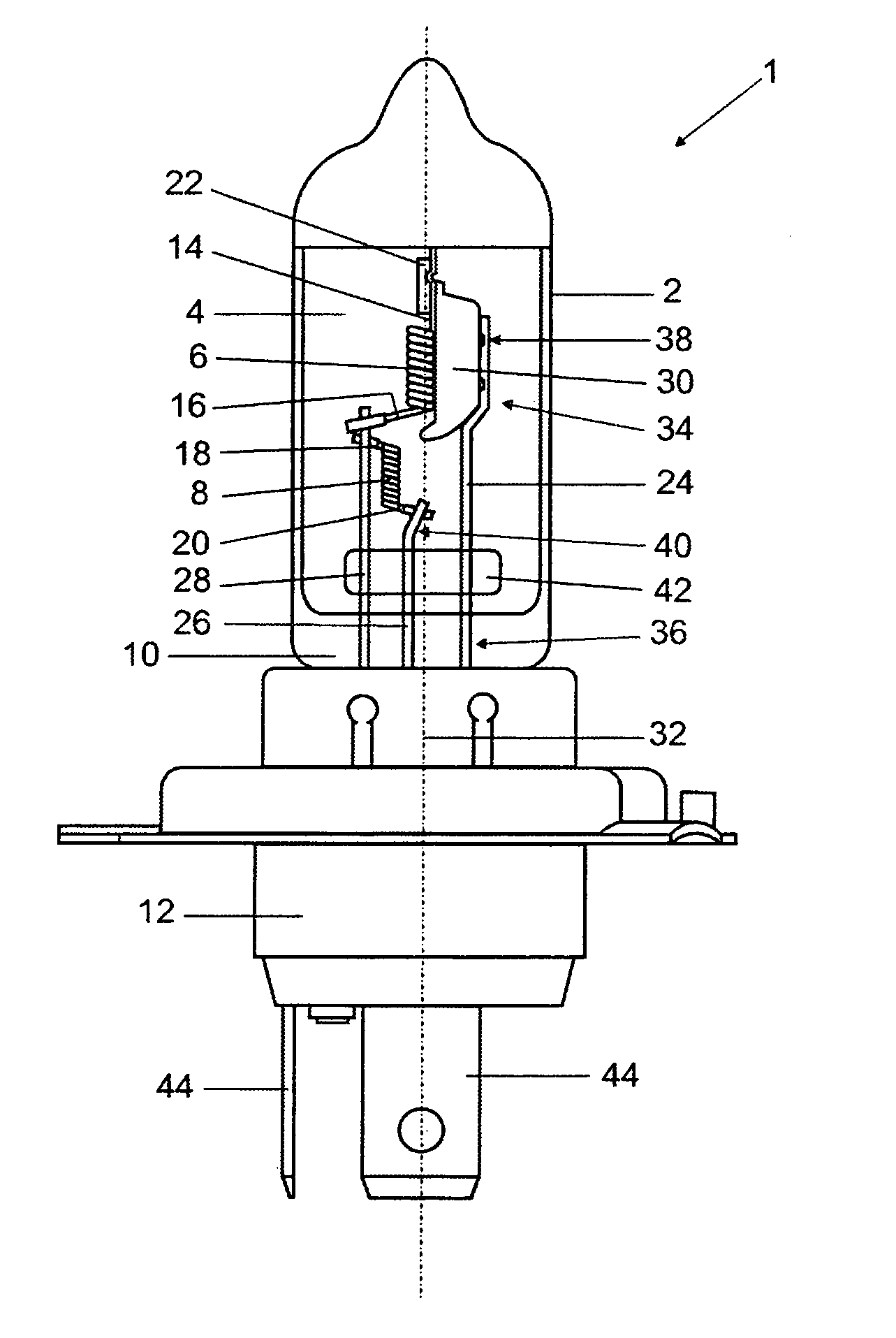
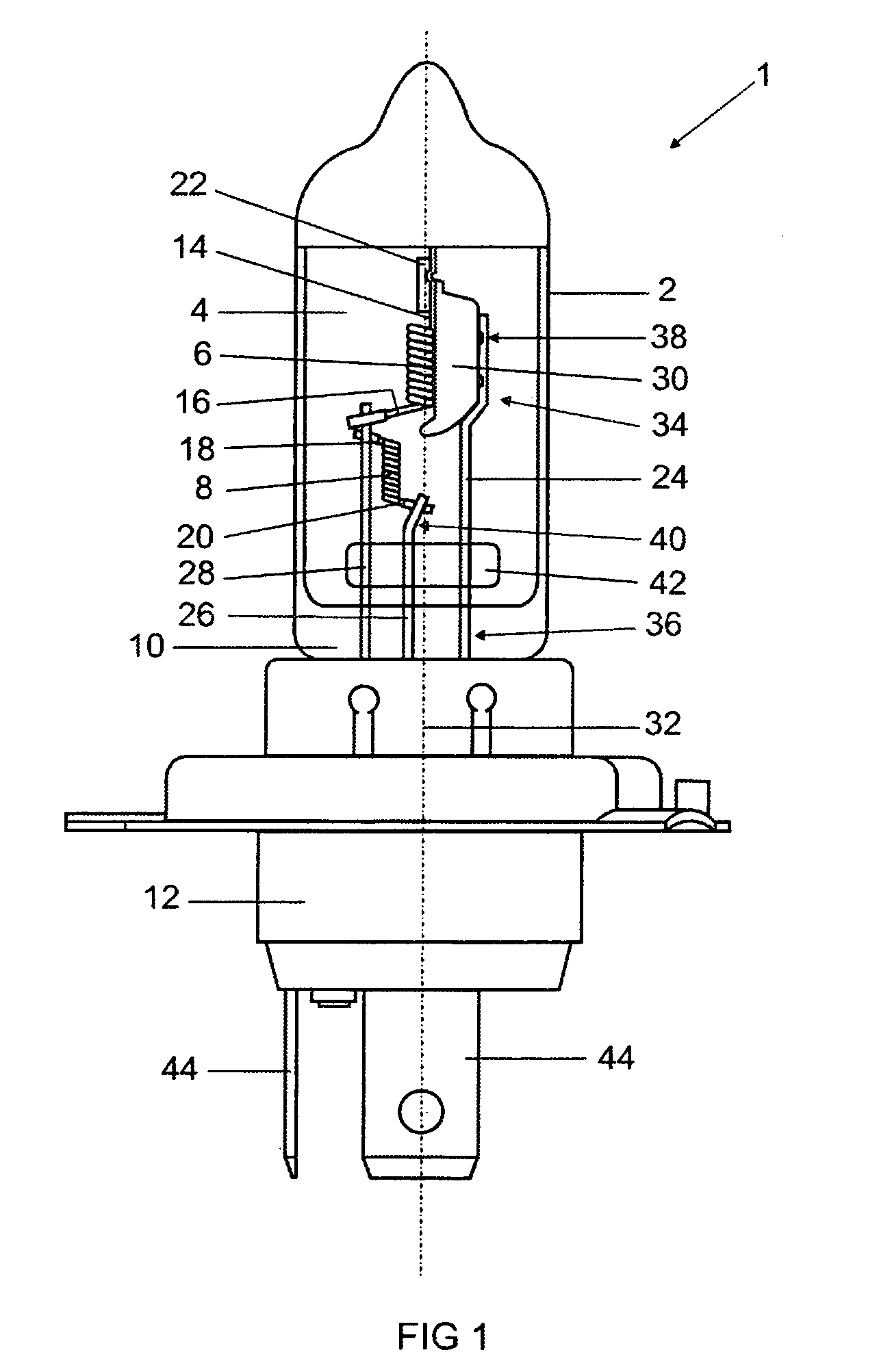
[0019]FIG. 1 shows a front view of an inventive lamp 1 designed as a halogen incandescent lamp, as is used in a vehicle headlight, for example. The lamp has a substantially cylindrical lamp vessel 2, in whose interior 4 there are arranged two incandescent filaments 6, 8 that are used, for example, to generate a high beam and a daytime running light or a high beam and a passing beam. The lamp vessel 2 is sealed via a pinch seal 10 at one end and inserted into a base 12. The outgoing filament lines 14, 16, 18, 20 of the incandescent filaments 6, 8 are respectively provided with a welding aid 22 and brought into electrical contact via supply lead wires 24, 26, 28. In the case of the illustrated alignment of the lamp 1, which corresponds to a preferred operating position of the inventive lamp 1 in the vehicle h...


PUM


Abstract

Disclosed is a lamp, particularly for a vehicle headlight, comprising two spiral-wound filaments which are retained by three feeders within a bulb that is inserted into a base. The feeders are arranged on top of one another when the lamp is adequately oriented. A tail of the first spiral-wound filament is connected to a dimming cap, said tail being located at a distance from the base, while a tail of the second spiral-wound filament is connected to the central feeder, said tail being close to the base. The second filament tail that faces away and is located at a distance from the base is connected to the upper feeder. According to the invention, the lower feeder is connected to the dimming cap by means of an end, some sections of which are angled away from a longitudinal axis of the lamp.

Description

[0001]This application is a U.S. National Phase Application under 35 USC 371 of International Application PCT / EP2007 / 063618, filed Dec. 10, 2007, which is incorporated herein in its entirety by this reference.TECHNICAL FIELD[0002]The invention relates to a lamp, in particular for a vehicle headlight, having two incandescent filaments that are held by three supply lead wires inside a lamp vessel inserted into a base, the supply lead wires being arranged one above another, given suitable alignment of the lamp, an outgoing filament line, remote from the base, of the first incandescent filament being connected to an anti-dazzle device, and an outgoing filament line, near the base, of the second incandescent filament being connected to the middle supply lead wire, and the outgoing filament line, averted from and remote from the base, being connected to the upper supply lead wire.PRIOR ART[0003]Such a lamp is disclosed, for example, in EP 1 667 205 A2 by the applicant. These conventional ...

Claims


Application Information

Patent Timeline
Patent Type & Authority Patents(United States)
IPC IPC(8): H01K1/00
CPCH01K1/18H01K1/40H01K9/08
Inventor AUER, FRANKBEHR, GERHARDHELBIG, PETERSEICHTER, CHRISTIANWITTMANN, KLAUSZELT, SASCHA
Owner OSRAM GMBH
Why Eureka
Try Eureka