Door release mechanism

a technology of door release and door shaft, which is applied in the direction of door/window protective devices, gearing, shutters/movable grilles, etc., can solve the problems of requiring structural alteration of the building to retrofit electronic fire door systems into the existing building, system design, installation and maintenance costs, and the inability to prevent the rotation of the brake drive sprocket, so as to facilitate the free rotation of the door shaft and prevent the rotation of the brake drive sprock

Active Publication Date: 2013-03-19
OVERHEAD DOOR
View PDF50 Cites 35 Cited by
  • Summary
  • Abstract
  • Description
  • Claims
  • Application Information

AI Technical Summary

Problems solved by technology

Such systems are costly to design, install, and maintain.
In addition, conventional electronic fire door systems are generally significantly larger than a standard door hoist.
As such, retrofitting electronic fire door systems into an existing building may require structural alteration of the building.
As a result, the installation and maintenance of electronic fire door systems may be cost prohibitive in some instances.

Method used


Image

  • Door release mechanism
  • Door release mechanism
  • Door release mechanism

Examples


Embodiment Construction

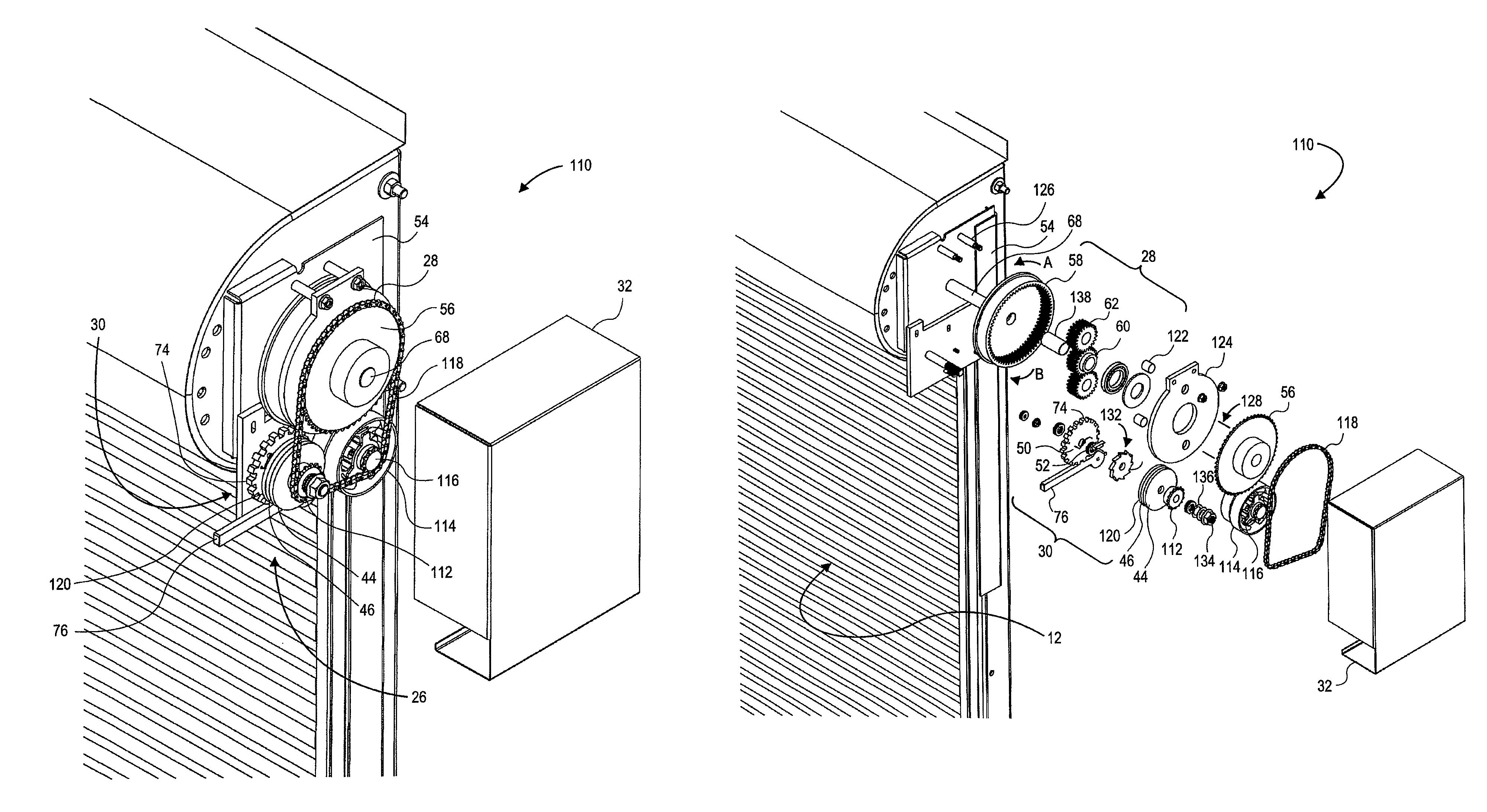
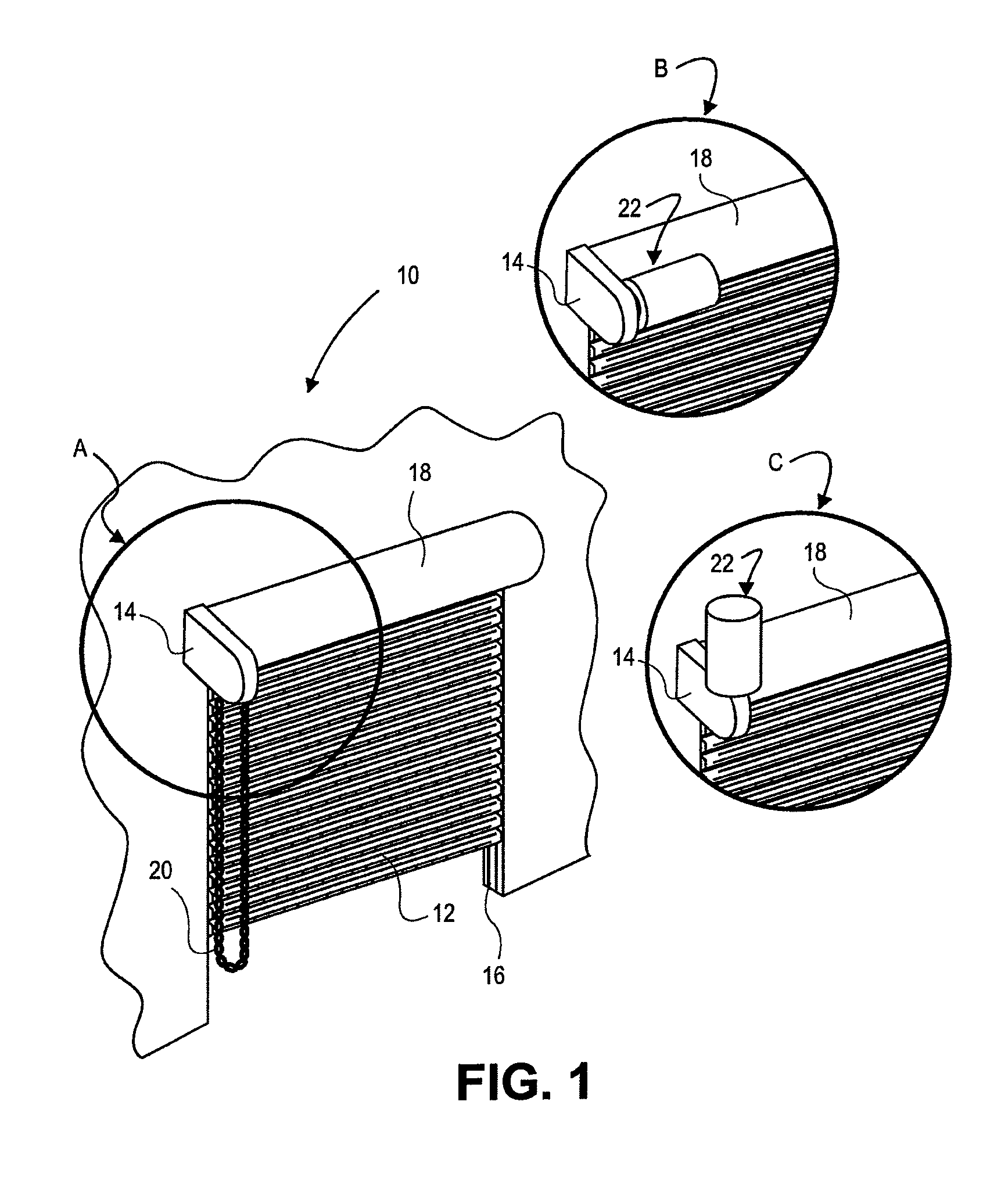
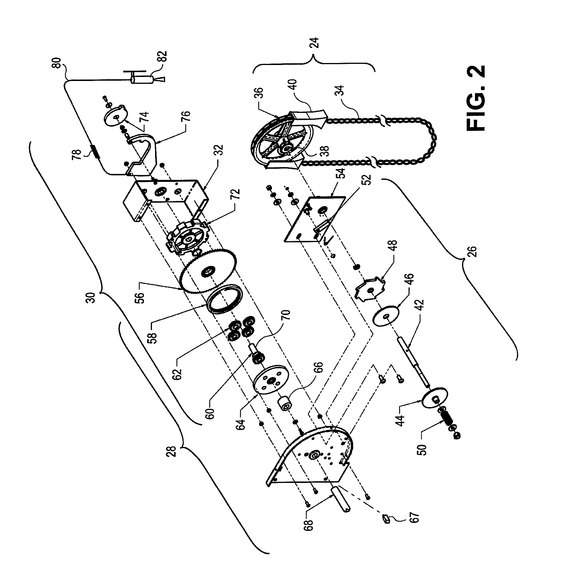
[0032]In various embodiments of the invention a simplified device and system are provided to automatically release a door in response to an event. In a particular example, the device is configured to close a door in the event of a fire. For example, when attached to a door that is biased to close, a release assembly connecting a hoist assembly to the door assembly may be configured to release the door assembly from the hoist assembly in response to a fire or smoke. Released from the hoist assembly, the door may be allowed to close. In another example, the release assembly may be configured to release the door assembly from the hoist assembly in response to a security incident. In yet another example, the release assembly connects the hoist assembly to a door assembly that is biased to open. In this example, the release may be controlled to release the door assembly from the hoist assembly to facilitate egress through the door. In comparison to electronically controlled or computer c...


PUM


Abstract

A door mechanism includes a bracket and a door shaft, rotationally mounted to the bracket, to operate a door. The door mechanism includes a gear assembly having a ring gear, set of planetary gears, sun gear, and drive sprocket. The ring gear fixed to the door shaft. The door mechanism includes a holding brake to counter the closing bias of the door. The door release has an engaged position in which rotation of the door shaft in the second direction is impeded by a first brake; and a disengaged position in which rotation of the door shaft in the second direction is unimpeded by the first brake. The door mechanism includes a link and a second brake. The link is configured to melt in response to a predetermined temperature. The second brake is configured to provide resistance in response to component rotation exceeding a predetermined speed.

Description

CLAIM OF PRIORITY[0001]This application claims the benefit of, U.S. Provisional Patent Application Ser. No. 61 / 170,888 filed Apr. 20, 2009, entitled DOOR RELEASE MECHANISM, the disclosure of which is incorporated herein by reference in its entirety.FIELD OF THE INVENTION[0002]The present invention generally relates to a door mechanism. More particularly, the present invention pertains to a device and system for automatically releasing a door in response to an event.BACKGROUND OF THE INVENTION[0003]Conventionally, door hoist systems are utilized to operate a variety of doors. Particular examples of doors operated via a door hoist include rolling type, sectional, and the like. These types of doors are typically utilized for controlling access to garages, ware houses, etc. In the event of a fire, it is generally beneficial to close these doors to limit the amount of oxygen supplied to the fire and slow the spread of fire from one side of the door to the other.[0004]Conventional electro...

Claims


Application Information

Patent Timeline
Patent Type & Authority Patents(United States)
IPC IPC(8): E05F15/20
CPCE05F15/20E05F15/1653E05F15/2007E05D13/003E05F15/71E06B9/70E06B5/16E05F15/684E05F15/70E06B9/08E05Y2900/106E06B2009/6818E05Y2900/00
Inventor DAUS, MARKEITERMAN, ALVIN R.
Owner OVERHEAD DOOR
Why Eureka
Try Eureka