Magnetic switching device

Active Publication Date: 2013-03-19
ROSENBERGER HOCHFREQUENZTECHNIK GMBH & CO KG
View PDF4 Cites 7 Cited by
  • Summary
  • Abstract
  • Description
  • Claims
  • Application Information

AI Technical Summary

Benefits of technology

[0014]A further advantage of the invention over the prior art is that the magnetic switching apparatus can be arranged, together with the two switching devices, in a housing from which just the switching element then projects.
[0015]As a result of this embodiment, premounting can be carried out for the entire switching apparatus, in which case it is ultimately only then necessary to assign the switching element to a driver element which activates it.
[0016]According to the invention, the switching element can be embodied, for example, as a switching tappet.
[0017]The separating plate made of ferromagnetic or magnetic material, for example a soft iron plate, can be of any desired shape and its shape is tailored according to the respective application switching point. All that is important is that it is smaller than the end faces, facing one another, of the magnets.
[0018]The core of the invention is based on this embodiment and the shape of the separating plate in rel

Problems solved by technology

However, a disadvantage for satisfactory functioning of the known switching apparatuses is that the movable components are usually elastically connected to the vehicle by means of seals.
This means that in the driving state relative movements can occur between the movable component and the vehicle, and vibrations may also be produced.
This risk occurs,

Method used


Image

  • Magnetic switching device
  • Magnetic switching device
  • Magnetic switching device

Examples


Embodiment Construction

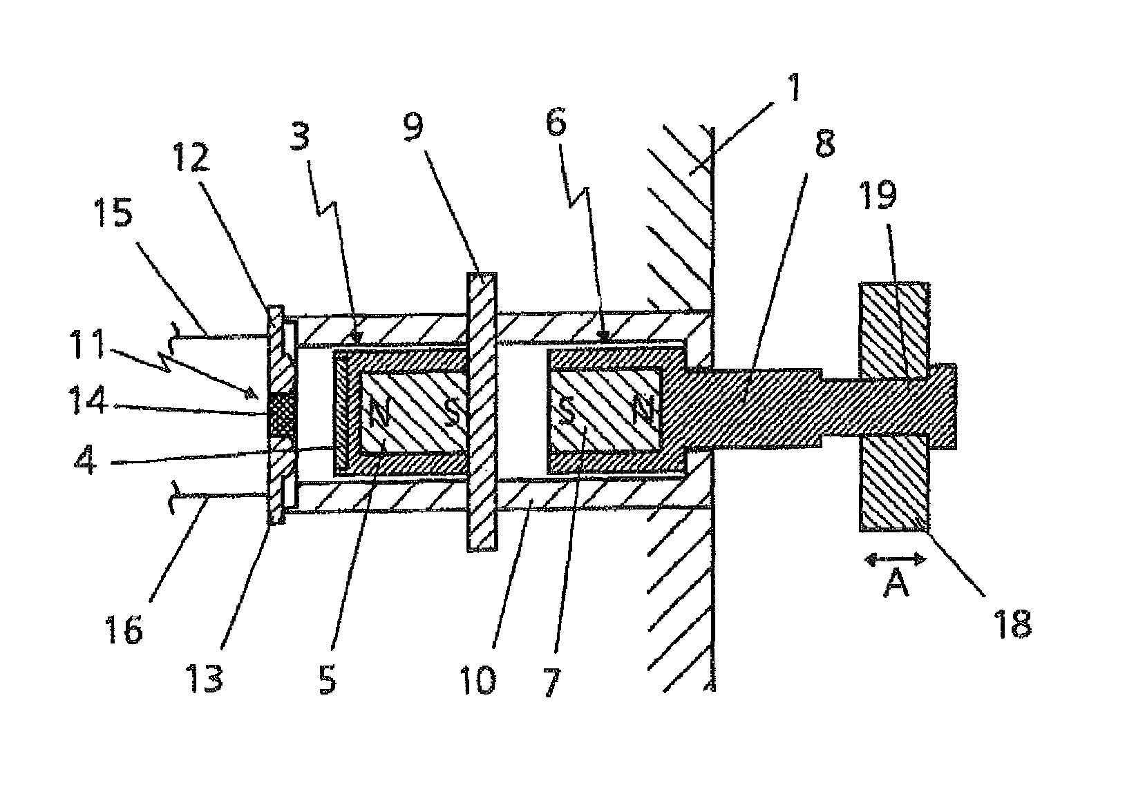
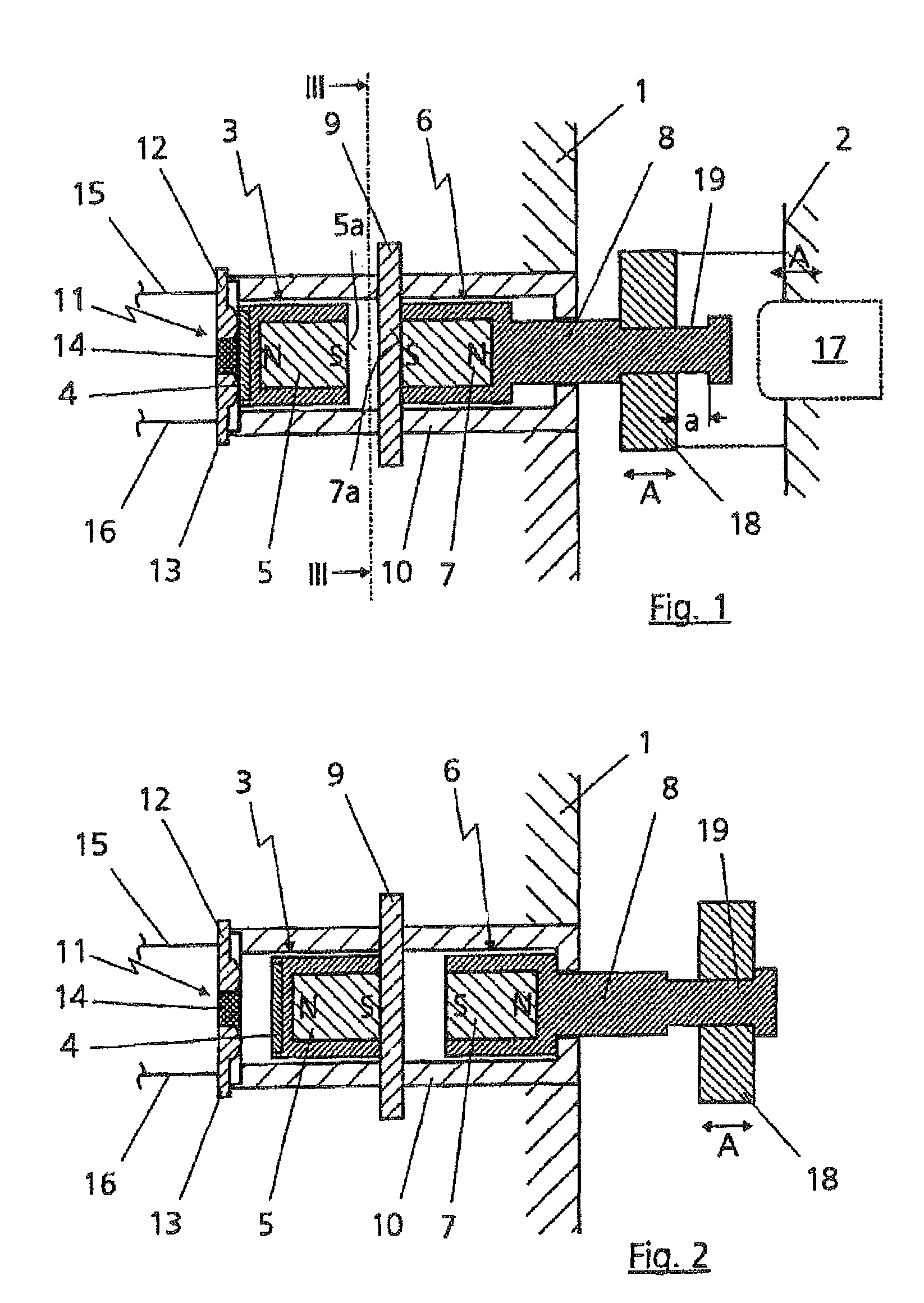
[0049]The apparatus according to the invention is described using an example for a vehicle wherein a component of the vehicle or of the vehicle frame 1 is intended to constitute as fixed element and a door, for example a sliding door 2, of the vehicle is intended to constitute as a movable element. However, of course, the apparatus according to the invention is also suitable for other elements in which relative movements or vibrations may occur between a first element and a second element, or there may be large tolerances present. Likewise, if appropriate both elements may also be movable with respect to one another.

[0050]Further application fields are, for example, machines, apparatuses and devices which are subject to strong vibrations or which are also arranged in mobile systems, machines and the like. Instead of being used to produce an electrical connection or a specific switched state, the apparatus according to the invention can, if necessary, also be used for mechanical swit...


PUM


Abstract

A magnetic switching device is provided with a first switching device which is provided with a movable magnet connected to a contact bridge, and with a second switching device which is provided with a magnet connected to a movable switch element. The magnets have the same polarity on the front faces facing each other. Positioned between the magnets is a separating plate made of ferromagnetic material, which is smaller than the front faces of the magnets which face each other.

Description

CROSS REFERENCE TO RELATED APPLICATIONS[0001]This is a U.S. National Phase Entry under 35 U.S.C. §371 of, and claims priority under 35 U.S.C. Sections 119(a)-d), 120, 363 and 365 to, International Application No. PCT / EP2008 / 001304, filed Feb. 20, 2008 which designated the United States and at least one other country in addition to the United States and claimed priority to German Application No. 10 2007 013 292.3, filed Mar. 16, 2007. The specifications of these applications are hereby expressly incorporated by reference in their entirety to form a part of this application.FIELD OF THE INVENTION[0002]The invention relates to a magnetic switching apparatus having a first switching device, which is provided with a movable magnet connected to a contact bridge, and having a second switching device, which is provided with a magnet which is connected to a movable switching element. The invention also relates to a magnetic switching apparatus for producing an electrical connection between a...

Claims


Application Information

Patent Timeline
IPC IPC(8): H01H9/00H01H3/48H01H5/02
CPCH01H36/0073H01H36/00
Inventor PFEIFFER, KLAUSKONZELMANN, ULRICH
Owner ROSENBERGER HOCHFREQUENZTECHNIK GMBH & CO KG
Why Eureka
Try Eureka