Hydraulic remote control for hydraulic system of an agricultural implement

a hydraulic system and remote control technology, applied in the field of agricultural implements, can solve the problems of reducing the space in the operator cab of the towing vehicle, adding to the complexity of the overall hydraulic system, etc., and achieve the effect of less complex

a hydraulic system and remote control technology, applied in the field of agricultural implements, can solve the problems of reducing the space in the operator cab of the towing vehicle, adding to the complexity of the overall hydraulic system, etc., and achieve the effect of less complex

US8408326B2Active Publication Date: 2013-04-02CNH IND CANADA

Image

  • Hydraulic remote control for hydraulic system of an agricultural implement
  • Hydraulic remote control for hydraulic system of an agricultural implement
  • Hydraulic remote control for hydraulic system of an agricultural implement

Examples


Embodiment Construction

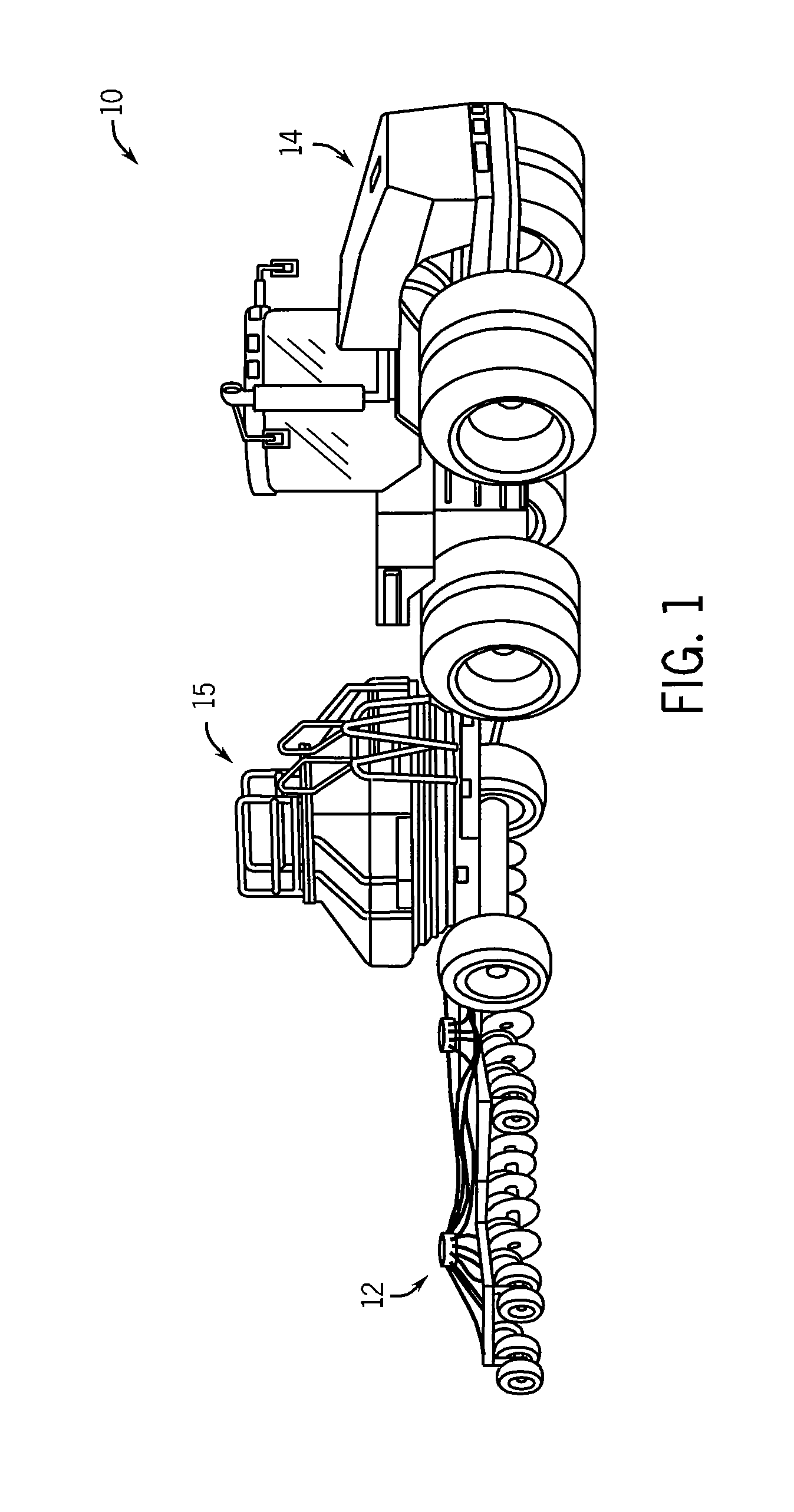
[0025]Referring now to FIG. 1, a planting system 10 according to one embodiment of the invention includes a foldable implement 12, shown in a field working position, coupled to a prime mover 14, e.g., tractor, in a known manner. The planting system 10 may also include an air cart 15, as known in the art. While the invention is applicable with different types of foldable implements, for purposes of illustration, the invention will be described with respect to a hoe drill.

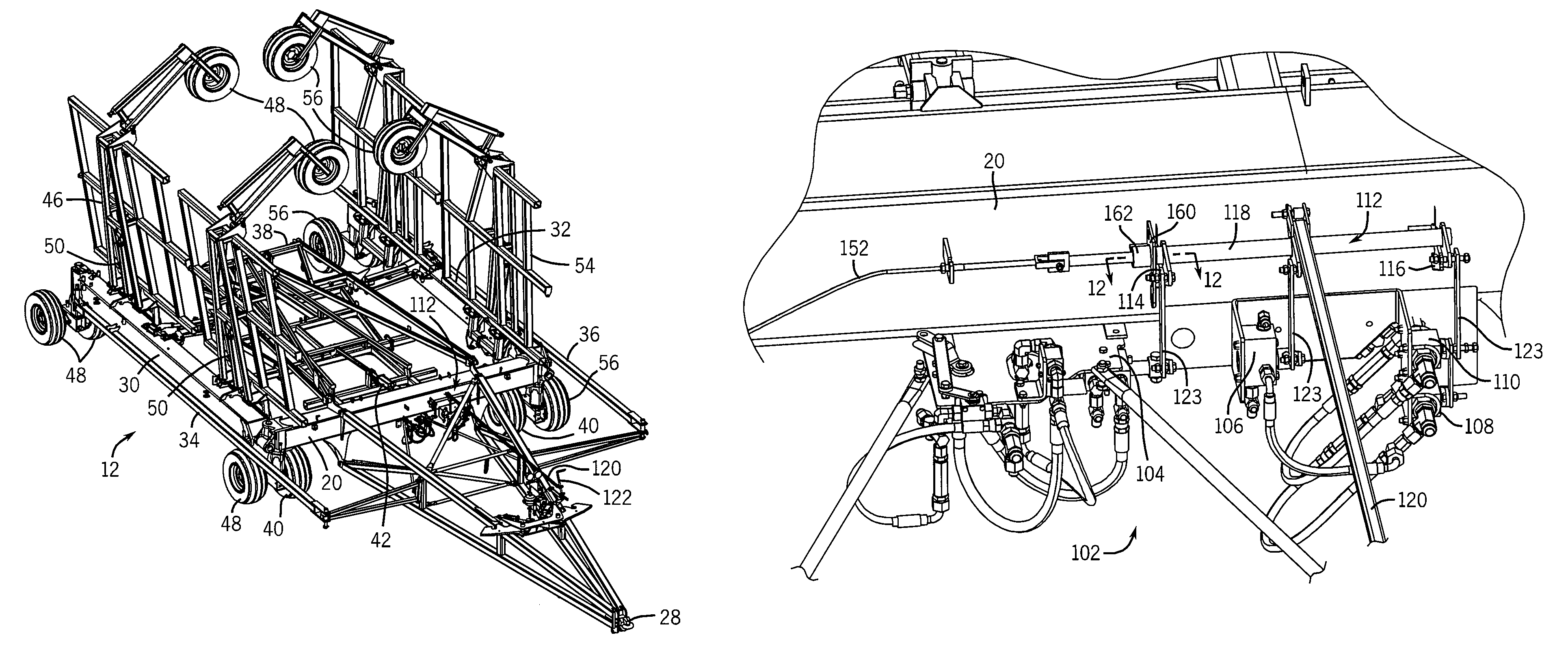
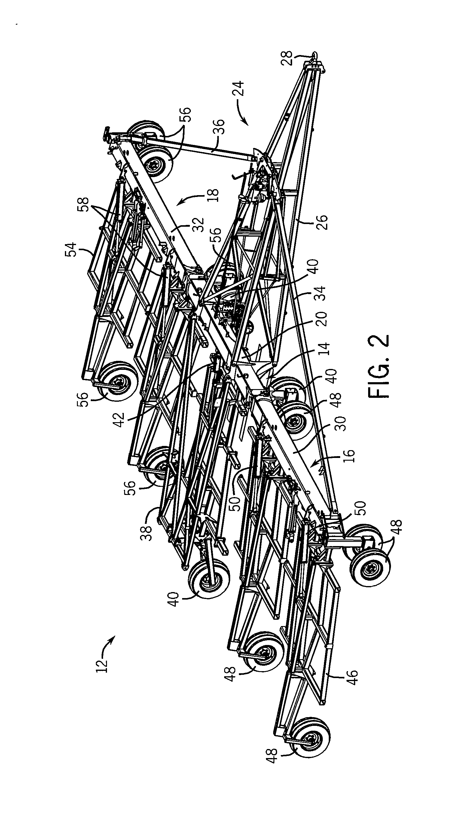
[0026]Referring now to FIG. 2, hoe drill 12 has a center frame section 14 and two wing sections 16, 18 pivotally mounted to opposite lateral sides of the center frame section 14. The wing sections 16, 18 are designed to be folded to a transport position in which the wing sections 16, 18 are folded over the center frame section 14 to provide a narrow transport configuration that is suited for transport between crops, fields, and along roadways, as well as storage. FIG. 3 shows the hoe drill 12 in the folded, transport...


PUM


Abstract

A hydraulic control apparatus for a foldable farm implement has a first hydraulic control system is used to control weight transfer to a plurality of ground engaging tools mounted to stationary and wing frame sections of the farm implement. A second hydraulic system is used to fold and unfold the wing sections for placing the implement in a compact position for transport and storage. A hydraulic control is provided that interfaces with both hydraulic systems to control sequencing of the functions provided by the first and second hydraulic systems.

Description

BACKGROUND OF THE INVENTION[0001]The present invention relates generally to farm implements and, more particularly, a hydraulic control system having a single remote hydraulic control.[0002]Modern farmers strive to improve the management of the increasing amounts of farm acres. Improving management requires farmers to be able to quickly prepare the soil and plant seed each season. This haste has driven the need for more efficient and larger agricultural machinery.[0003]Implements such as harrows, packers, or combined harrow-packers are being made with widths exceeding sixty feet in the field operating position. Also, drill implements employed to distribute seed product across an agricultural field are also being made increasingly wider in the field operating position. Wider working widths provide more efficient field working such as by increasing the number of rows that are seeded in a single pass or by increasing the amount of field that is tilled in a single pass. However, as agri...

Claims


Application Information

Patent Timeline
02 Apr 2013
Publication
US8408326B2
IPC
A01B63/00
CPC
A01B73/048; A01B73/065; F15B11/20; F15B2211/50518; F15B2211/50554; F15B2211/7121; F15B2211/7128; F15B2211/783
Inventors
YUEN, CORY ADRIAN; RYDER, NICHOLAS