Method of manufacturing polarizing eyeglass lens

a manufacturing method and technology of polarizing eyeglasses, applied in the field of polarizing eyeglasses, can solve the problems of polarizing lenses, inability to fully block diagonally polarized light entering from such diagonal directions, and polarization of light that can be blocked

Inactive Publication Date: 2013-04-09
HOYA CORP
View PDF12 Cites 0 Cited by
  • Summary
  • Abstract
  • Description
  • Claims
  • Application Information

AI Technical Summary

Benefits of technology

[0014]An aspect of the present invention provides for a method of manufacturing a polarizing eyeglass lens that can block light having different directions of polarization that enters from various directions.
[0024]In particular, when the displacement reference is set on the substrate to form rubbing traces, it is possible to form polarization axes that are closed curves in the form of concentric circles. Thus, it becomes possible to handle reflected light entering from any direction over a 360 degree range.
[0025]In the present invention, a polarizing layer can be formed in which the directions of polarization axes vary continuously, making it possible to provide a polarizing eyeglass lens that is capable of blocking light with different directions of polarization entering from various directions.

Problems solved by technology

Thus, the polarizing lens of US2008 / 0252846A1 is incapable of fully blocking diagonally polarized light that enters from such diagonal directions.
When the directions of polarization axes are varied in each zone, the directions of polarization of the light that can be blocked are limited, numerous variations must be prepared based on use by the wearer, and difficulty is to be anticipated in responding to the needs of customers.
Further, it is inconvenient for the wearer to carry all of these variations around with him and change out the lenses as needed.
Thus, this is not a desirable polarizing lens.

Method used


Image

  • Method of manufacturing polarizing eyeglass lens
  • Method of manufacturing polarizing eyeglass lens
  • Method of manufacturing polarizing eyeglass lens

Examples


first modification example

(3-2) First Modification Example

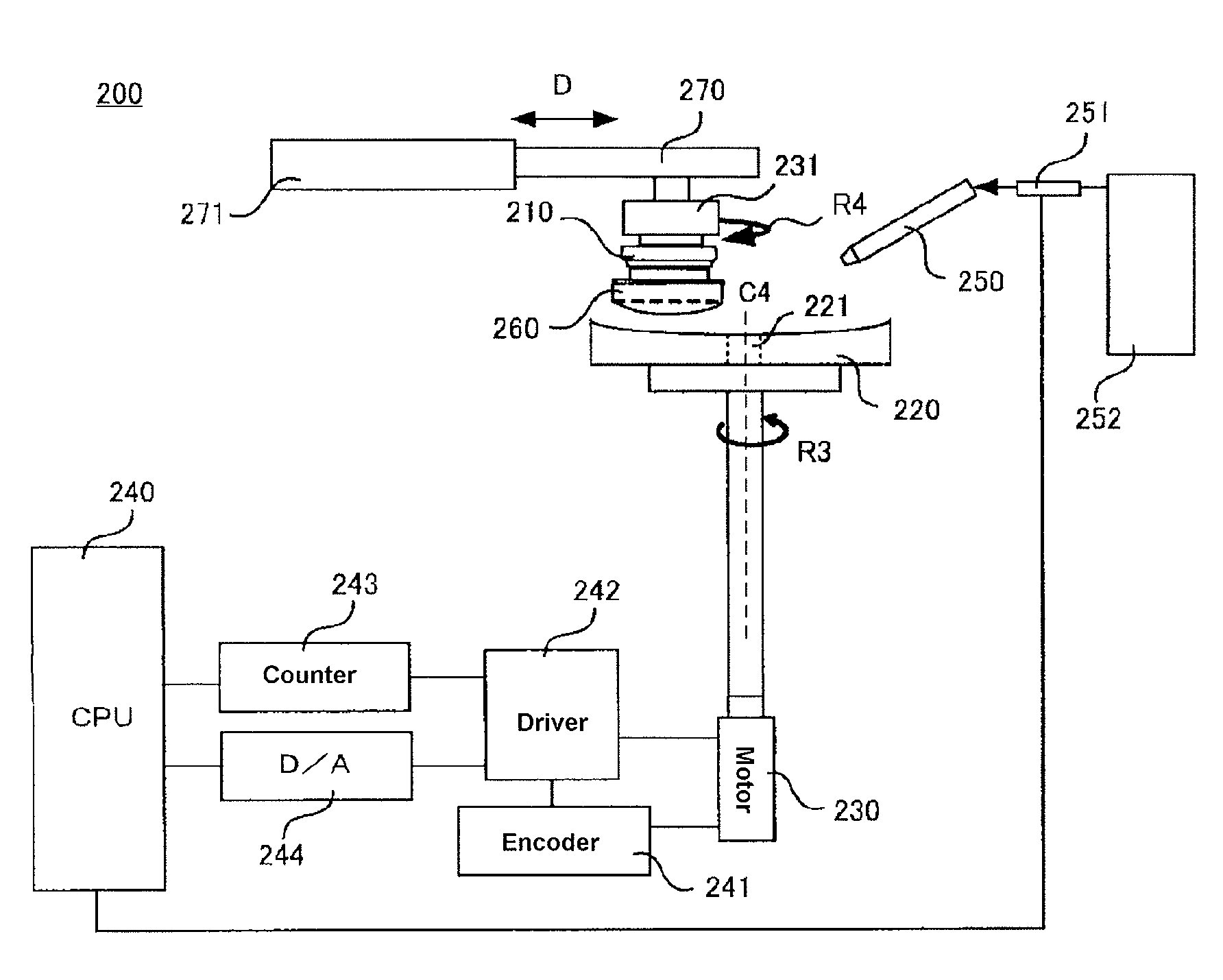
[0118]This is an example in which the rubbing member is secured and the substrate is displaced by revolution. FIG. 5 is a drawing showing the steps of forming rubbing traces in this example. FIG. 5A is a top view when forming rubbing traces, and FIG. 5B is a side view. In the present modification example, in addition to the steps of forming rubbing traces described using FIG. 5, it is also possible to manufacture polarizing lenses by the same steps as those shown in above-described FIG. 1.

[0119]As shown in FIG. 5A, in the present example, rubbing head 24 is secured. Substrate 20 is secured on jig 23 with the side on which the orientation layer (not shown) is formed facing upward. Rod-shaped shaft 26 is connected to jig 23. Displacement reference 27 is provided at a position at some distance from jig 23 on shaft 26, and is secured by a support member, not shown. As shown in FIG. 5B, rubbing member 25 is mounted to the bottom of head 24. Rubbing member ...

second modification example

(3-3) Second Modification Example

[0124]In the present modification example, a surface plate is employed instead of securing a rubbing member to the head. The surface plate is rotated as a rubbing member to form rubbing traces on the orientation layer on the substrate. Except for the step of forming the rubbing traces, manufacturing can be conducted by the same manufacturing steps as those described with reference to FIG. 1 in the present modification example.

[0125]FIG. 6 is a top view showing the step of forming rubbing traces in the present example. As shown in FIG. 6, on surface plate 31 of any desired size, for example, on a circular surface plate, substrate 30 on which has been formed an orientation layer is secured to a separate support (not shown) so as not to rotate with surface plate 31 and so that the surface of the orientation layer faces surface plate 31 side as the sliding surface. It is positioned away from the center of surface plate 31.

[0126]An elastic member such as ...

third modification example

(3-4) Third Modification Example

[0131]In the present modification example, a surface plate is secured and the substrate is displaced by revolution with a displacement reference positioned away from the substrate as the center axis to conduct processing and form an orientation layer provided with arc-shaped rubbing traces. Except for the step of forming the rubbing traces that is described using FIG. 7, manufacturing can be conducted as in the other modification examples by the same manufacturing steps as those described with reference to FIG. 1.

[0132]FIG. 7 is a top view of the steps of forming rubbing traces in the present modification example. Substrate 40 on which has been formed an orientation layer comprised of a sol-gel film, an SiO2 layer, or the like is secured to jig 43 with the side on which the orientation layer has been formed facing surface plate 41. Rod-shaped shaft 46, for example, is connected to jig 43, and substrate 40 is displaced by revolution about displacement ...


PUM

PropertyMeasurementUnit
outer diameteraaaaaaaaaa
thicknessaaaaaaaaaa

Abstract

An aspect of the present invention relates to a method of manufacturing a polarizing eyeglass lens comprising forming an orientation layer on a substrate, sliding a rubbing member across the orientation layer in a state of contact with the orientation layer to form curved rubbing traces on a surface of the orientation layer, forming a polarizing layer by depositing and orienting a dichroic dye on the orientation layer, and subjecting the polarizing layer to a treatment of immobilizing the dichroic dye in the polarizing layer.

Description

CROSS-REFERENCE TO RELATED APPLICATIONS[0001]This application claims the benefit of priority under 35 USC 119 to Japanese Patent Application No. 2009-182885 filed on Aug. 5, 2009 and Japanese Patent Application No. 2010-166738 filed on Jul. 26, 2010, which are expressly incorporated herein by reference in their entirety.BACKGROUND OF THE INVENTION[0002]1. Field of the Invention[0003]The present invention relates to a method of manufacturing a polarizing eyeglass lens functioning to absorb or transmit light of a specific direction of polarization for the purpose of blocking light such as reflected light having a specific direction of polarization outdoors or the like.[0004]2. Discussion of the Background[0005]A variety of polarizing elements that pass or block only those components of incident light that are polarized in specific directions have come into use. For example, in optical pickups, there are glass elements that comprise multilayered films and diffraction gratings comprised...

Claims


Application Information

Patent Timeline
Patent Type & Authority Patents(United States)
IPC IPC(8): B29D11/00
CPCG02C7/12
Inventor WATANABE, YOSHIFUMIYAJIMA, EIICHI
Owner HOYA CORP
Why Eureka
Try Eureka