
Slot line volumetric antenna

a volumetric antenna and slot line technology, applied in the field of wireless communication, can solve the problems of limiting the widespread adoption of directional antennas, noticeably reducing the gain of monopole antennas,

Active Publication Date: 2018-10-04
AMI RES & DEV
View PDF3 Cites 3 Cited by
  • Summary
  • Abstract
  • Description
  • Claims
  • Application Information

AI Technical Summary

Benefits of technology

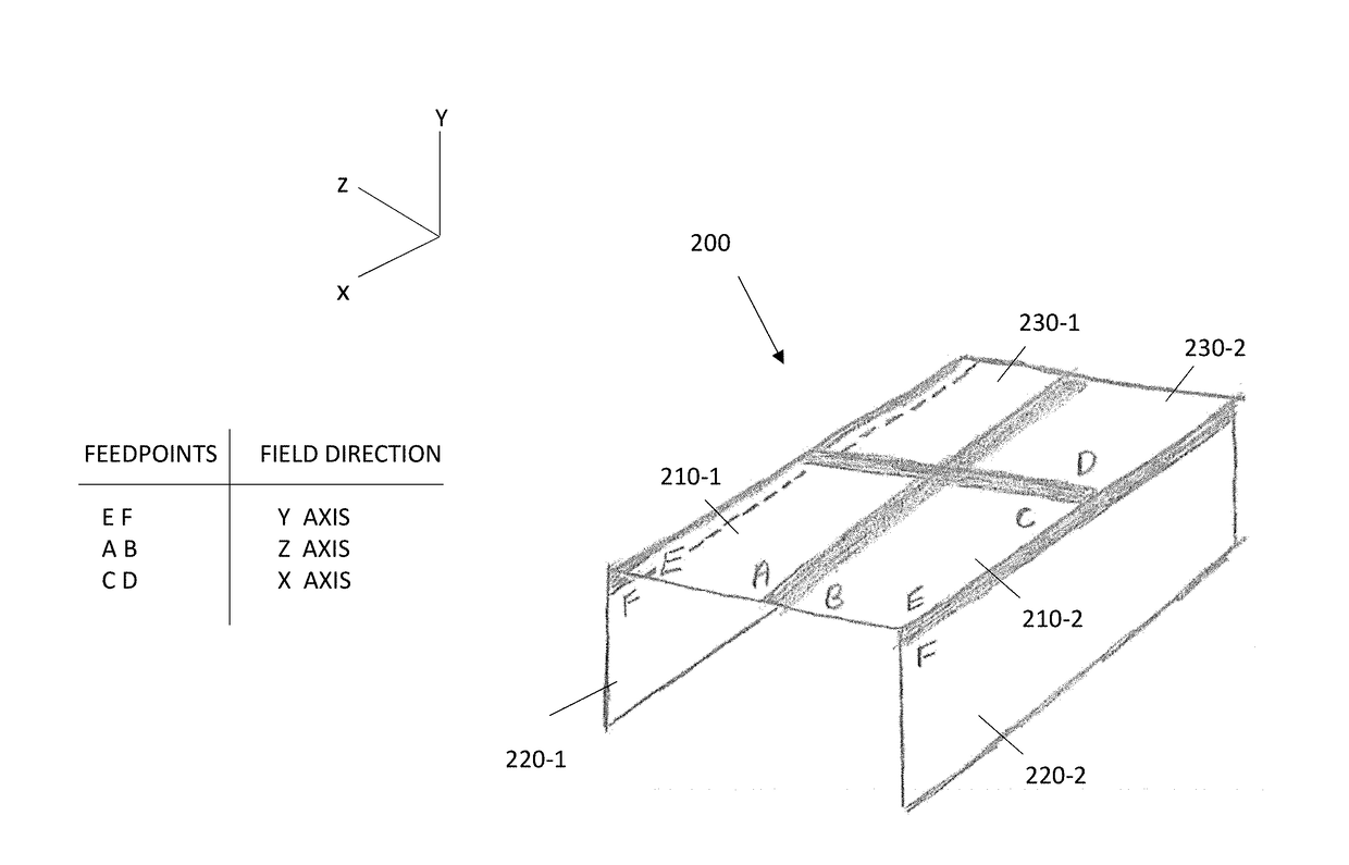
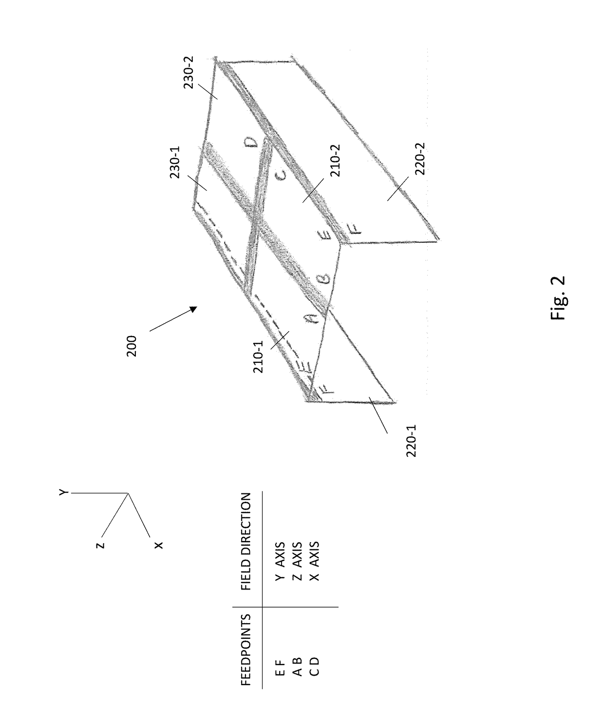
The volumetric antenna element presented in this patent allows fordirectional radiation and multiple polarizations. It consists of planar conductive patches that form a "u" shape in cross section, circumscribing a volume. The elements can be controlled to reflect or direct a beam of radiation along one of three axes. The elements may be arranged in a parasitic configuration to provide multiple input / output (MIMO) operation. The element can be utilized in a wireless device, providing different polarizations through a combining circuit. The technical effects of the invention include improved antenna performance and improved MIMO capabilities in a compact design.

Problems solved by technology

However, the gain of a monopole antenna is noticeably reduced by the proximity of a nearby human user.
Such regulations, as well as a general concern over potentially adverse health effects resulting from concentrated radio frequency emissions, have limited the widespread adoption of directional antennas.

Method used


Image

  • Slot line volumetric antenna
  • Slot line volumetric antenna
  • Slot line volumetric antenna

Examples


Embodiment Construction

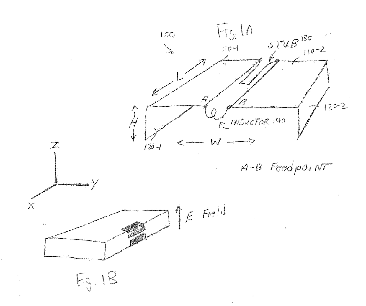
[0024]One example implementation of a slot line antenna element 100 is shown on the upper right of FIG. 1A. A pair of conductive material patches 110-1, 110-2 disposed in a first plane are spaced apart by a slot. Each patch is folded over in an L-shape, such that a other conductive sections 120-1, 120-2 are located in another, preferably perpendicular or orthogonal plane. The patches 110-1, 120-1 mirror patches 110-2, 120-2. The patches may be r, typically to conform to the edge of a device housing, as shown in the middle of the figure. A first feed point A is provided at one end of one patch 110-1, and a second feed point B is provided on the other patch 110-2. Length L is typically 0.2 wavelengths, while height H and width W are in the 0.1 wavelength range.

[0025]The volumetric slot line element 100 may include a hairpin stub 130 on the end opposite the A,B feedpoints, which extends the effective length to ¼ wavelengths. An inductor 140 placed across the feedpoints helps resonate t...


PUM


Abstract

A slot fed volumetric antenna structure that activates antenna beams in three axes by selective connection of feedpoints.

Description

CROSS REFERENCE TO RELATED APPLICATIONS[0001]This application claims priority to a co-pending U.S. Provisional Patent Application Ser. No. 62 / 463,086 filed Feb. 24, 2017 entitled “Slot Line OMAN Antenna” and is also related to co-pending U.S. patent application Ser. No. 15 / 362,988 filed Nov. 29, 2016 entitled “Super Directive Array of Volumetric Antenna Elements for Wireless Device Applications”. The entire contents of each of these applications is hereby incorporated by reference.BACKGROUNDTechnical Field[0002]This application relates to wireless communication and in particular to a volumetric antenna element with a controllable beam direction.Background Information[0003]An important consideration in the design of a wireless device is the antenna. The operating frequency, bandwidth, size constraints, and likelihood of perturbation by the surrounding environment often dictate the antenna configuration. Handheld wireless devices such as cellular telephones have typically used a monop...

Claims


Application Information

Patent Timeline
Patent Type & Authority Applications(United States)
IPC IPC(8): H01Q3/24H01Q5/48H01Q5/45H01Q9/28H01Q21/24
CPCH01Q1/245H01Q3/247H01Q5/48H01Q5/45H01Q9/285H01Q21/245H01Q1/2291H01Q13/10H01Q21/08H01Q21/205H01Q21/26H01Q21/28H01Q25/00H01Q25/001
Inventor APOSTOLOS, JOHN T.MOUYOS, WILLIAMFENG, JUDY
Owner AMI RES & DEV
Learn More