Increasing efficiency of wireless power transfer

a wireless power transfer and efficiency technology, applied in the field of systems, can solve the problems of not allowing feedback to increase not providing such features in the foregoing systems based on inductive coupling or resonant inductive coupling, and not allowing such devices to control the wireless power transfer, etc., to achieve the effect of increasing the efficiency of wireless power transfer

Active Publication Date: 2013-04-23
AVAGO TECH INT SALES PTE LTD
View PDF48 Cites 27 Cited by
  • Summary
  • Abstract
  • Description
  • Claims
  • Application Information

AI Technical Summary

Benefits of technology

[0018]A system and / or method for increasing efficiency of wireless power transfer, substantially as shown in and / or described in connection with at least one of the figures, as set forth more completely in the claims.

Problems solved by technology

Unfortunately, none of the foregoing systems based on inductive coupling or resonant inductive coupling provide such features.
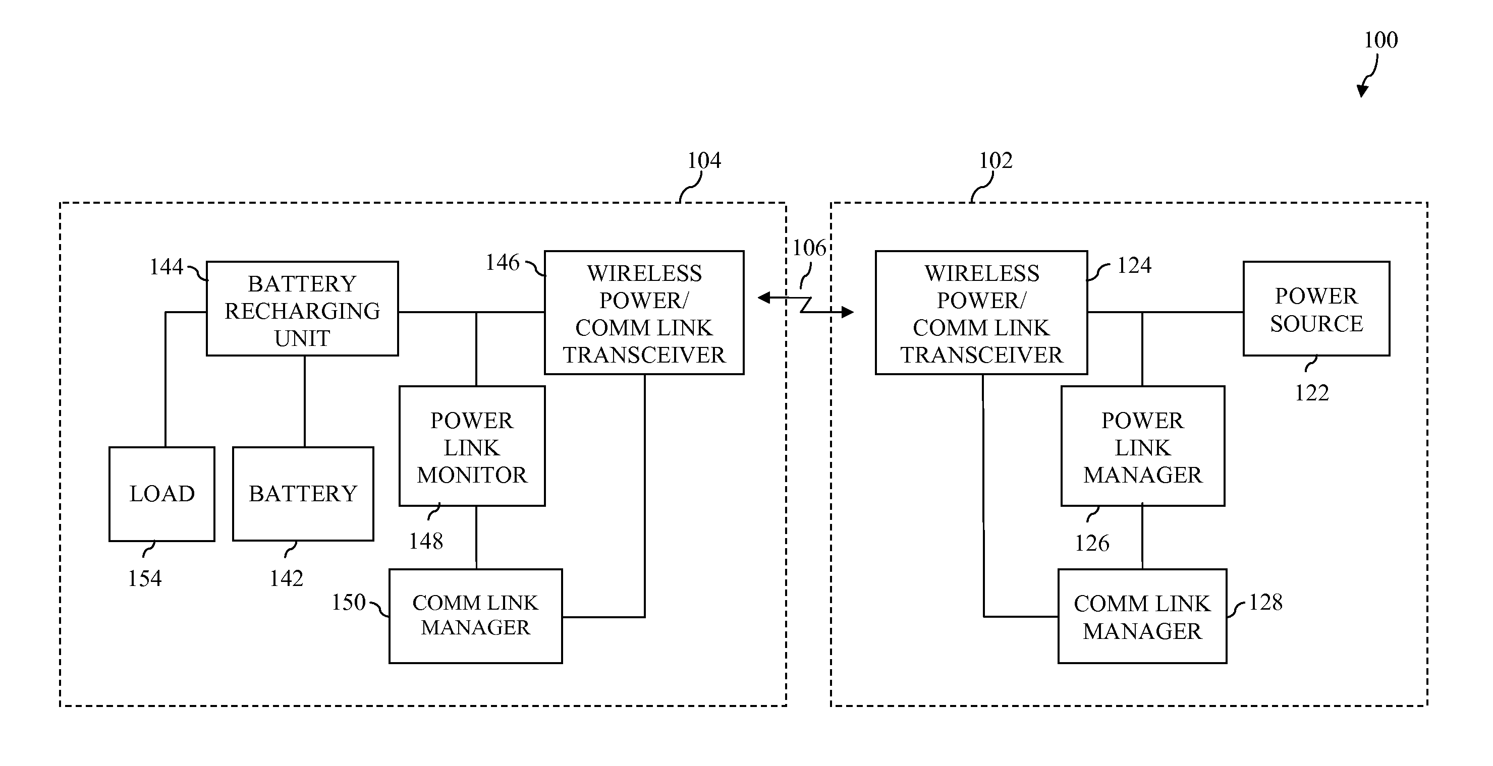
For example, although NFC devices may use magnetic field induction to wirelessly transfer power as well as payment information and other types of data, it does not appear that such NFC devices are designed to use the wirelessly transferred power to recharge a power source associated with a portable electronic device.
Furthermore, it does not appear that such devices control the wireless power transfer based on parameters and / or state information received from the portable electronic device having a power source to be recharged.
Moreover, conventional techniques for transferring power wirelessly do not allow for feedback to increase efficiency of the wireless power transfer.

Method used


Image

  • Increasing efficiency of wireless power transfer
  • Increasing efficiency of wireless power transfer
  • Increasing efficiency of wireless power transfer

Examples


Embodiment Construction

I. Introduction

[0034]The following detailed description refers to the accompanying drawings that illustrate example embodiments of the present invention. However, the scope of the present invention is not limited to these embodiments, but is instead defined by the appended claims. Thus, embodiments beyond those shown in the accompanying drawings, such as modified versions of the illustrated embodiments, may nevertheless be encompassed by the present invention.

[0035]References in the specification to “one embodiment,”“an embodiment,”“an example embodiment,” or the like, indicate that the embodiment described may include a particular feature, structure, or characteristic, but every embodiment may not necessarily include the particular feature, structure, or characteristic. Moreover, such phrases are not necessarily referring to the same embodiment. Furthermore, when a particular feature, structure, or characteristic is described in connection with an embodiment, it is submitted that i...


PUM


Abstract

Techniques are described herein that are capable of increasing efficiency of wireless power transfer. A wireless power transfer system includes features that allow the system to be deployed in public spaces such as airports or in commercial establishments such as restaurants or hotels to allow a user to recharge one or more portable electronic devices while away from home. To accommodate wireless recharging of a variety of device types and states, the system may receive parameters and/or state information associated with a portable electronic device to be recharged and may control the wireless power transfer in accordance with such parameters and/or state information. For instance, the system may increase efficiency of the wireless power transfer based on such parameters and/or state information. The system may also provide a secure and efficient means for obtaining required payment information from the user prior to the wireless power transfer, thereby facilitating fee-based recharging.

Description

CROSS-REFERENCE TO RELATED APPLICATIONS[0001]This application is a continuation-in-part of U.S. patent application Ser. No. 12 / 421,762, filed Apr. 10, 2009, which claims the benefit of U.S. Provisional Application No. 61 / 150,554, filed Feb. 6, 2009, the entireties of which are incorporated by reference herein.BACKGROUND OF THE INVENTION[0002]1. Field of the Invention[0003]The invention generally relates to systems capable of transmitting electrical power without wires.[0004]2. Background[0005]As used herein, the term wireless power transfer refers to a process by which electrical energy is transmitted from a power source to an electrical load without interconnecting wires. Wireless power transfer is useful for applications in which instantaneous or continuous energy transfer is needed, but for which providing a wired connection is inconvenient, hazardous, or impossible.[0006]It has been observed that while electromagnetic radiation (such as radio waves) is excellent for transmitting...

Claims


Application Information

Patent Timeline
Patent Type & Authority Patents(United States)
IPC IPC(8): H02J7/04H02J7/00
CPCH02J17/00H02J5/005H02J7/025B60L11/182H01M10/46H02J7/00H01F38/14H02J50/90B60L53/126H02J7/00034Y02T10/70Y02T10/7072Y02T90/14Y02E60/10H02J50/80H02J50/12
Inventor VORENKAMP, PIETERVAN DER LEE, REINIERVAN LOO, INSUN
Owner AVAGO TECH INT SALES PTE LTD
Why Eureka
Try Eureka