
Wireless power maximum efficiency tracking by system control

a technology of system control and maximum efficiency, applied in the direction of electric variable regulation, process and machine control, instruments, etc., can solve the problem that the overall efficiency of the transmit/receiver system is not much attention, and achieves the effect of improving the efficiency of the wireless power transfer, increasing the power provided, and decreasing efficiency

Active Publication Date: 2020-03-05
INTEGRATED DEVICE TECH INC
View PDF0 Cites 2 Cited by
  • Summary
  • Abstract
  • Description
  • Claims
  • Application Information

AI Technical Summary

Benefits of technology

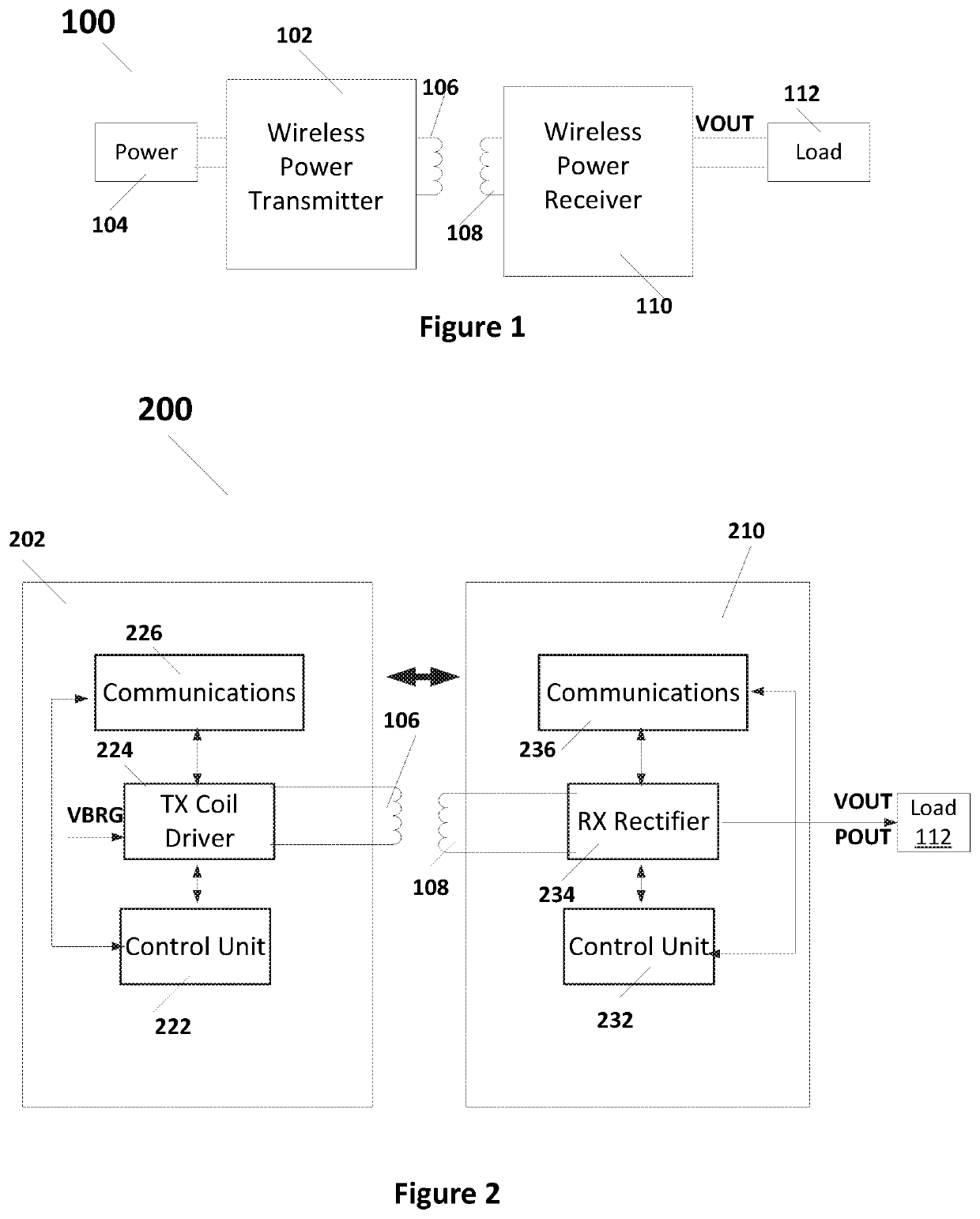
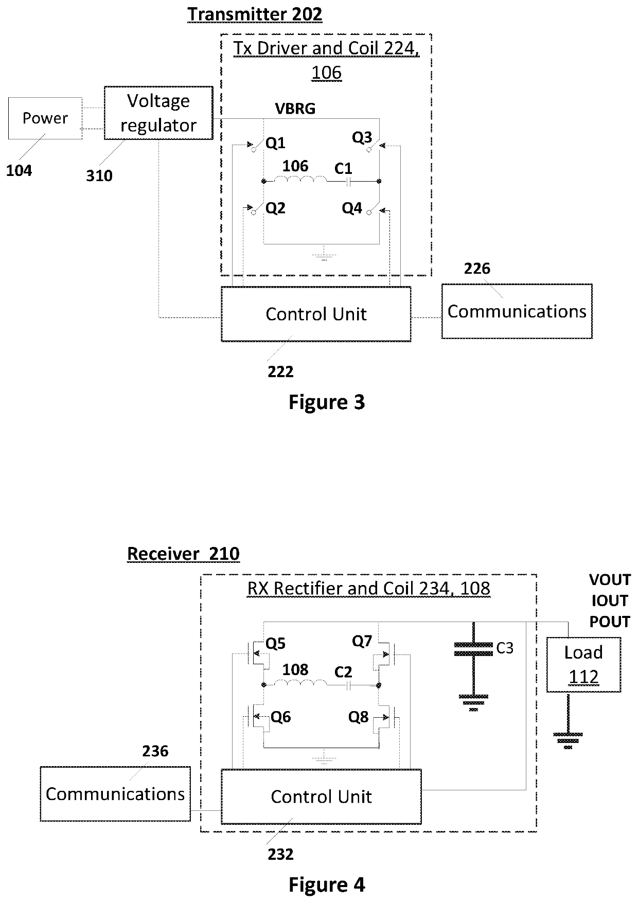
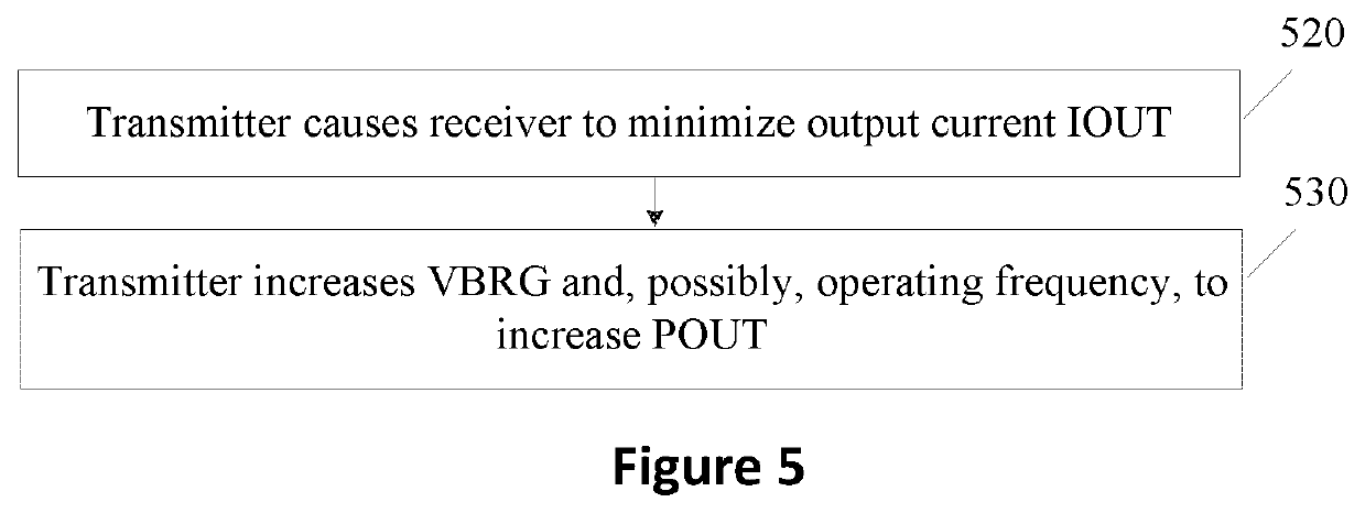
The patent text describes a way to improve the efficiency of wireless power transfer between a transmitter and a receiver. This is done by reducing the current in the receiving coil and increasing the power provided to the receiver without decreasing efficiency. The transmitter reduces the current in the receiver's coil and adjusts its operating parameters to provide more power to the receiver. These adjustments can include increasing the voltage or changing the operating frequency. The technical effect of this method is improved efficiency in wireless power transfer.

Problems solved by technology

Although systems have been designed to deliver required power to the receiver (RX) load, not much attention has been given to maximizing the overall efficiency of the transmit / receiver system as a whole.

Method used


Image

  • Wireless power maximum efficiency tracking by system control
  • Wireless power maximum efficiency tracking by system control
  • Wireless power maximum efficiency tracking by system control

Examples


Embodiment Construction

[0016]In the following description, specific details are set forth describing some embodiments of the present invention. It will be apparent, however, to one skilled in the art that some embodiments may be practiced without some or all of these specific details. The specific embodiments disclosed herein are meant to be illustrative but not limiting. One skilled in the art may realize other elements that, although not specifically described here, are within the scope and the spirit of this disclosure.

[0017]This description and the accompanying drawings that illustrate inventive aspects and embodiments should not be taken as limiting—the claims define the protected invention. Various changes may be made without departing from the spirit and scope of this description and the claims. In some instances, well-known structures and techniques have not been shown or described in detail in order not to obscure the invention.

[0018]Elements and their associated aspects that are described in det...


PUM


Abstract

In a wireless power transfer operation, the operating parameters are adjusted to improve efficiency by reducing the transmit and receive coil currents as follows. First, the transmitter causes the receiver to reduce the receive coil current to the lowest value based on the transmitter / receiver communication while still delivering the same amount of power to the load as before the AC current was adjusted to the minimum value. Then the transmitter may change the operating parameters to increase or preserve the power provided to the receiver without decreasing efficiency or with only small decrease in efficiency, or with increasing the efficiency. For example, the transmitter may increase the VBRG voltage (the DC voltage powering the transmit coil) or the operating frequency to maintain or increase output power levels at lower or the same AC and DC current levels. Other features are also provided.

Description

CROSS REFERENCE TO RELATED APPLICATIONS[0001]The present application claims priority to U.S. provisional patent application No. 62 / 724,519, filed Aug. 29, 2018, incorporated herein by reference.TECHNICAL FIELD[0002]Embodiments of the present invention are related to wireless power systems and, specifically, to wireless power maximum efficiency tracking by system controls.DISCUSSION OF RELATED ART[0003]Mobile devices, for example smart phones and tablets, are increasingly using wireless power charging systems. Typically, a wireless power charging system includes a transmitter coil that is driven to produce a time-varying magnetic field and a receiver coil that is positioned relative to the transmitter coil to receive the power transmitted in the time-varying magnetic field. Although systems have been designed to deliver required power to the receiver (RX) load, not much attention has been given to maximizing the overall efficiency of the transmit / receiver system as a whole.[0004]Ther...

Claims


Application Information

Patent Timeline
Patent Type & Authority Applications(United States)
IPC IPC(8): H02J50/12H02J50/80H02J7/02
CPCH02J50/12H02J50/80H02J7/025H02J50/10G05F1/67H02J3/0075H02J7/0047H04B5/79
Inventor SMITH, NICHOLAUSLIU, RUIBAVISI, AMIT D.HUANG, JIANGJIANAUNGURENCEI, GABRIEL
Owner INTEGRATED DEVICE TECH INC
Learn More