Internal combustion engine with toroidal cylinders

a technology of internal combustion engine and toroidal cylinder, which is applied in the field of machines, can solve the problems of long run time, reduced efficiency, and reduced efficiency of internal combustion engine, and achieves the effects of reducing emissions, superior performance, and lightening weigh

Inactive Publication Date: 2009-05-14
RAHON JOHN R
View PDF19 Cites 2 Cited by
  • Summary
  • Abstract
  • Description
  • Claims
  • Application Information

AI Technical Summary

Benefits of technology

[0019]Still another object of the present invention is to provide an internal combustion engine that provides superior performance and reduced emissions.
[0020]It is a further object of the present invention to provide an internal combustion engine that has fewer moving parts, is lighter in weight and smaller in size than a conventional engine of comparable power.
[0021]It is yet a further object of the present invention to provide an engine in which the mechanical forces are dynamically balanced and the thermal stress is evenly distributed.
[0022]It is still yet a further object of the present invention to provide an internal combustion engine that requires fewer and simpler seals that has reduced requirements for cooling and lubrication.
[0023]The above cited objects have been achieved by providing a torodial internal combustion engine with lengthened pistons that move through three perpendicularly intersecting torodial cylinders. The torus of each cylinder is formed of two substantially similar rings, a front ring member and a rear ring member. The ring members which form each toroidal cylinder are sealed along the seams to form the complete torus. The torus thus forms the chamber walls and the faces of the pistons form the boundaries within the torus. The engine includes one central power ring and a pair of charge rings which intersect opposite quadrants of the power ring at right angles to supply a fuel / air mixture to the power ring for combustion. One set of two pistons rotate within the power ring connected to opposite sides of a rotor while one set of two pistons, connected to charge rotors, rotate around each of two charge rings which feed the fuel and air charges to the power ring for combustion. The charge rotors are connected to the power rotor through a gear-train, so that all of the rotors rotate at the same rate. In operation, rotation of the charge rotors causes the pistons to move within the charge ring, allowing a charge of fresh air to be drawn into the charge ring. Further rotation of the engine causes the pistons of the power ring to cross the toroidal cylinders of the charge rings causing the air charge to be compressed against a side surface of the power piston and fuel is injected into the compressed charge of air. As the piston rotation progresses, the compressed fuel / air mixture is transferred to the power ring whereby the sides of the charge pistons and the rear surface of the power pistons form a pair of combustion chambers. A pair of spark plugs mounted in proximity to the combustion chambers ignite the fuel / air mixture expanding the charges to drive the power pistons further around the ring, causing exhaust gasses on the front sides of the power pistons to be expelled through ports or valves to an exhaust manifold, completing the cycle. The power rotor is suitably keyed to an output shaft to allow the rotational output of the power rotor to be used for useful work. In addition, the construction of the engine is such that multiple engines can be coupled to the output shaft to increase the power provided for work.

Problems solved by technology

They can be run for a very long time, because they're low RPM and are dimensioned for constant running.
Even though the reciprocating engine is available in so many configurations, the design still suffers from numerous disadvantages.
One major disadvantage is that the energy released by combustion is converted to work via linearly moving pistons and is then converted to rotational work output when it is transmitted to the crankshaft.
This transfer of work output from linear to rotational motion is inherently inefficient for several reasons.
For one, the slider crank mechanism that receives the work output from the piston is not at an optimum position for producing high torque on the crankshaft when pressure in the combustion chamber peaks and, consequently, only a portion of the energy generated by the combustion process is transmitted to the crankshaft, with the rest being dissipated in side thrust resulting in frictional work.
However, the combustion chambers are divided by blades which do have contact with both the walls and the rotor, and are said to have been difficult to seal due to the perpendicular intersection with the moving impeller.
One drawback to the prior art toroidal engines is the requirement that the pistons move in a stepwise fashion.
Stopping and restarting the piston movement requires a substantial amount of energy.

Method used


Image

  • Internal combustion engine with toroidal cylinders
  • Internal combustion engine with toroidal cylinders
  • Internal combustion engine with toroidal cylinders

Examples


Embodiment Construction

[0037]While the present invention is susceptible of embodiment in various forms, there is shown in the drawings and will hereafter be described a presently preferred embodiment with the understanding that the present disclosure is to be considered an exemplification of the invention and is not intended to limit the invention to the specific embodiments illustrated.

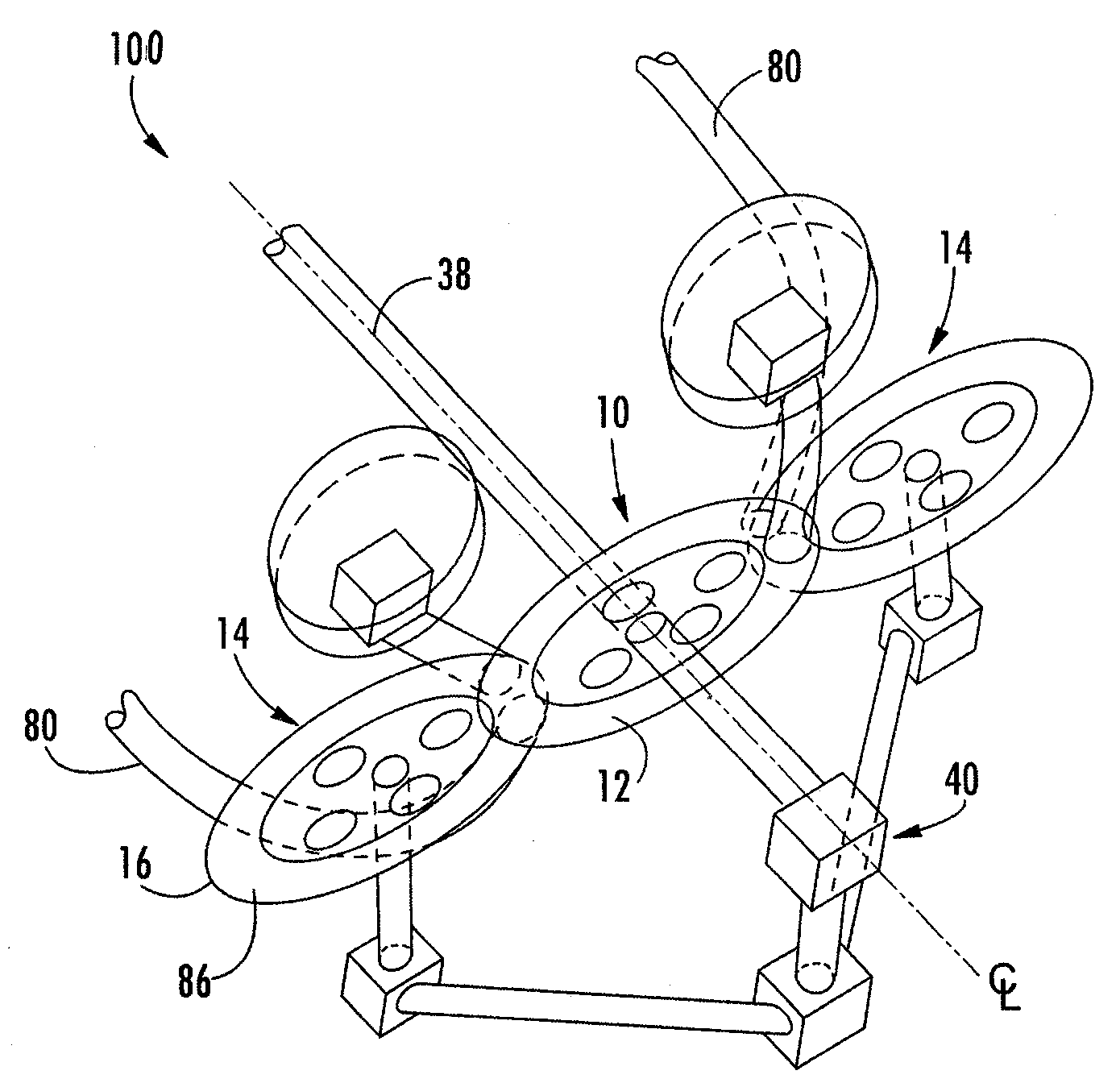
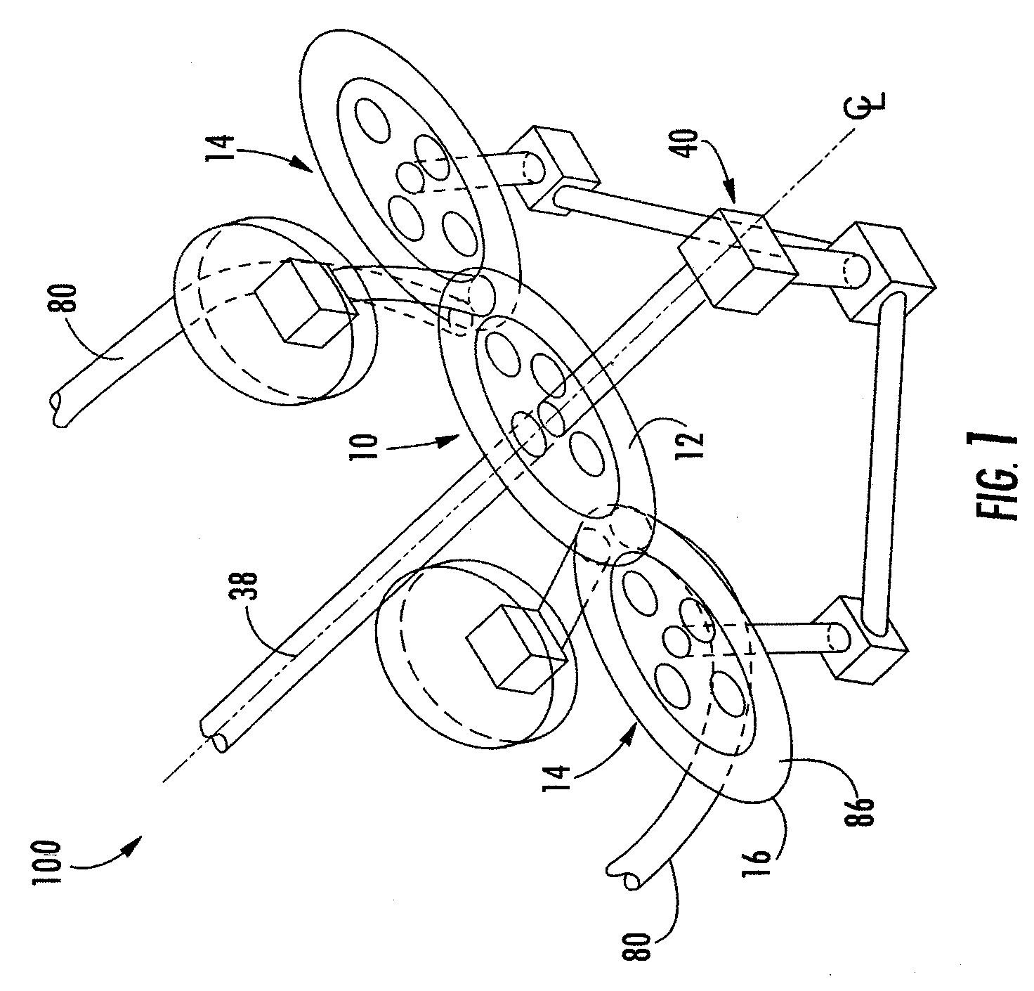
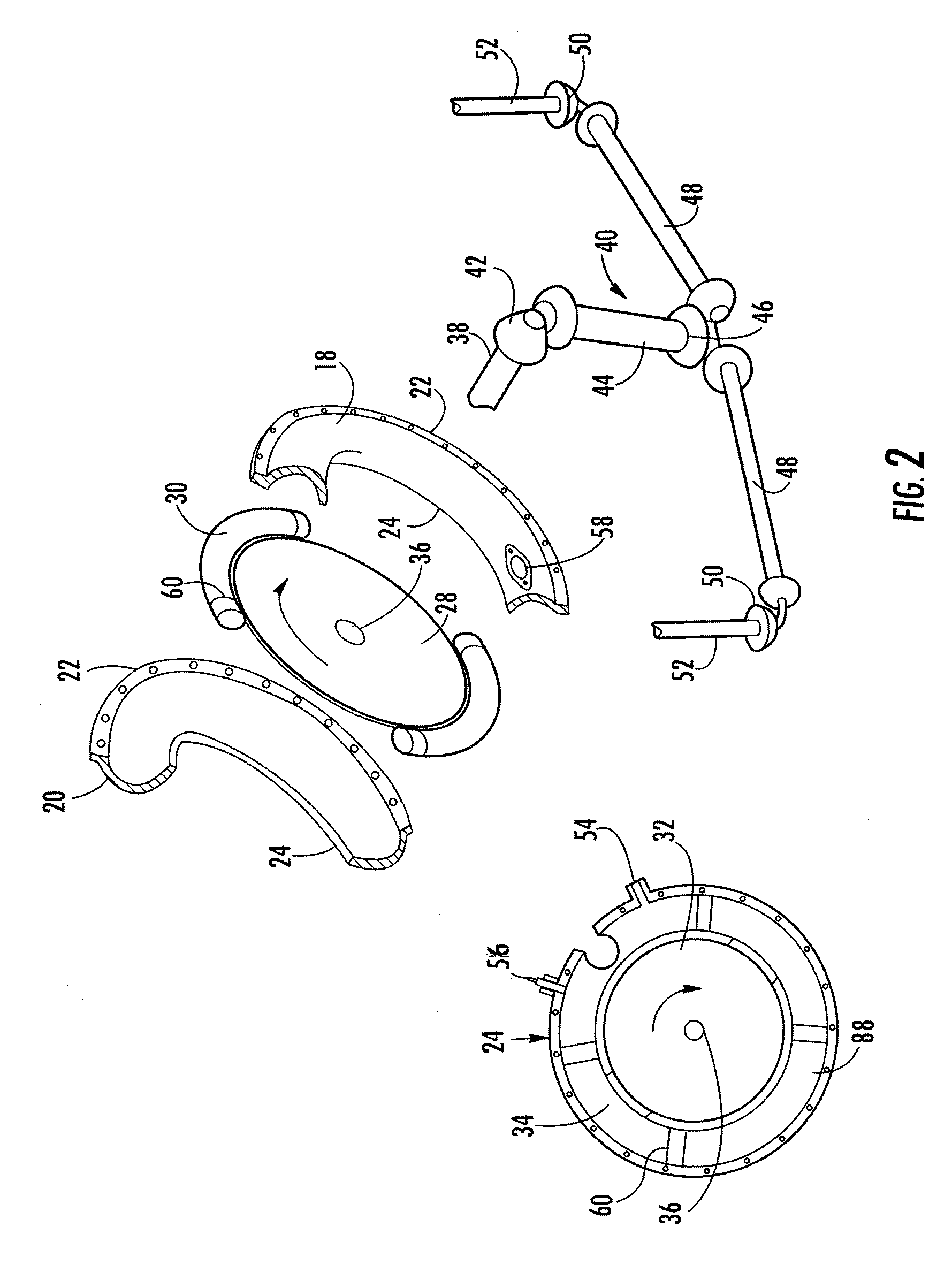
[0038]Referring to FIGS. 1 and 2, the internal combustion engine with torodial cylinders (100) is illustrated. In general, the engine includes a vertically oriented central power ring (10) having a torodial shaped cylinder (12). The power ring (10) is intersected by a pair of horizontally oriented charge rings (14) also having torodial shaped cylinders (16). The charge rings are positioned to intersect opposite quadrants of the power ring (10) at substantially right angles. The power ring (10) is comprised of two substantially similar halves, one being a front engine ring member (18) and the other being a rear engine ring ...


PUM


Abstract

The instant invention provides a torodial internal combustion engine with lengthened pistons that move through three perpendicularly intersecting torodial cylinders. The engine includes one central power ring and a pair of charge rings which intersect opposite quadrants of the power ring at right angles to supply a fuel/air mixture to the power ring for combustion. The charge rotors are connected to the power rotor, through a gear-train, so that all of the rotors rotate at the same rate. The fuel/air mixture is combusted within a combustion chamber formed entirely within the power ring.

Description

RELATED APPLICATIONS[0001]This application is related to U.S. Disclosure Document No. 600415 entitled The Rayhoon Engine filed May 9, 2006, the contents of which are incorporated herein in their entirety.FIELD OF THE INVENTION[0002]This invention pertains generally to machines such as engines, pumps and the like and more particularly, to a positive displacement internal combustion engine with toroidal shaped cylinders.BACKGROUND OF THE INVENTION[0003]For more than a century, internal combustion engines have been relied upon as a principal source of power in a variety of applications. Of those engines, the most widely used are the reciprocating piston engines which are found in automobiles or other forms of transportation, as well as a variety of industrial and consumer applications. Such engines can be built in a variety of sizes, types and configurations depending on the power requirements of a particular application. Generally, the engine configuration affects the physical size an...

Claims


Application Information

Patent Timeline
Patent Type & Authority Applications(United States)
IPC IPC(8): F02B53/08
CPCF01C3/02Y02T10/17F02B53/08Y02T10/12
Inventor RAHON, JOHN R.
Owner RAHON JOHN R
Why Eureka
Try Eureka