Image forming apparatus

a technology of forming apparatus and forming tube, which is applied in the direction of electrographic process apparatus, instruments, optics, etc., can solve problems such as paper jams, and achieve the effect of reducing the degree of improper separation jams

Inactive Publication Date: 2013-04-23
CANON KK
View PDF11 Cites 1 Cited by
  • Summary
  • Abstract
  • Description
  • Claims
  • Application Information

AI Technical Summary

Benefits of technology

[0011]A principal object of the present invention is to provide an image forming apparatus capable of reducing a degree of an occurrence of improper separation jam in the case where pre-print paper is subjected to additional fixing (in the case of multiple fixing).

Problems solved by technology

Then, when improper separation occurs, a paper jam is caused.
Specifically, in the case where the toner image is formed with the wax-containing transparent toner on a print (so-called pre-print paper) outputted by another apparatus, i.e., on the recording material on which the toner image has been fixed once (in the case of multiple fixing), the following problem arises.
That is, in the case where the image is formed on the pre-print paper with the toner containing no wax, when the image is intended to be formed only at a part of the pre-print paper with the wax-containing toner, the toner containing no wax is melted and the pre-print paper is caught in a fixing device, thus causing the jam.

Method used


Image

  • Image forming apparatus
  • Image forming apparatus
  • Image forming apparatus

Examples


embodiment 1

[Embodiment 1]

(1) General Structure of Image Forming Apparatus

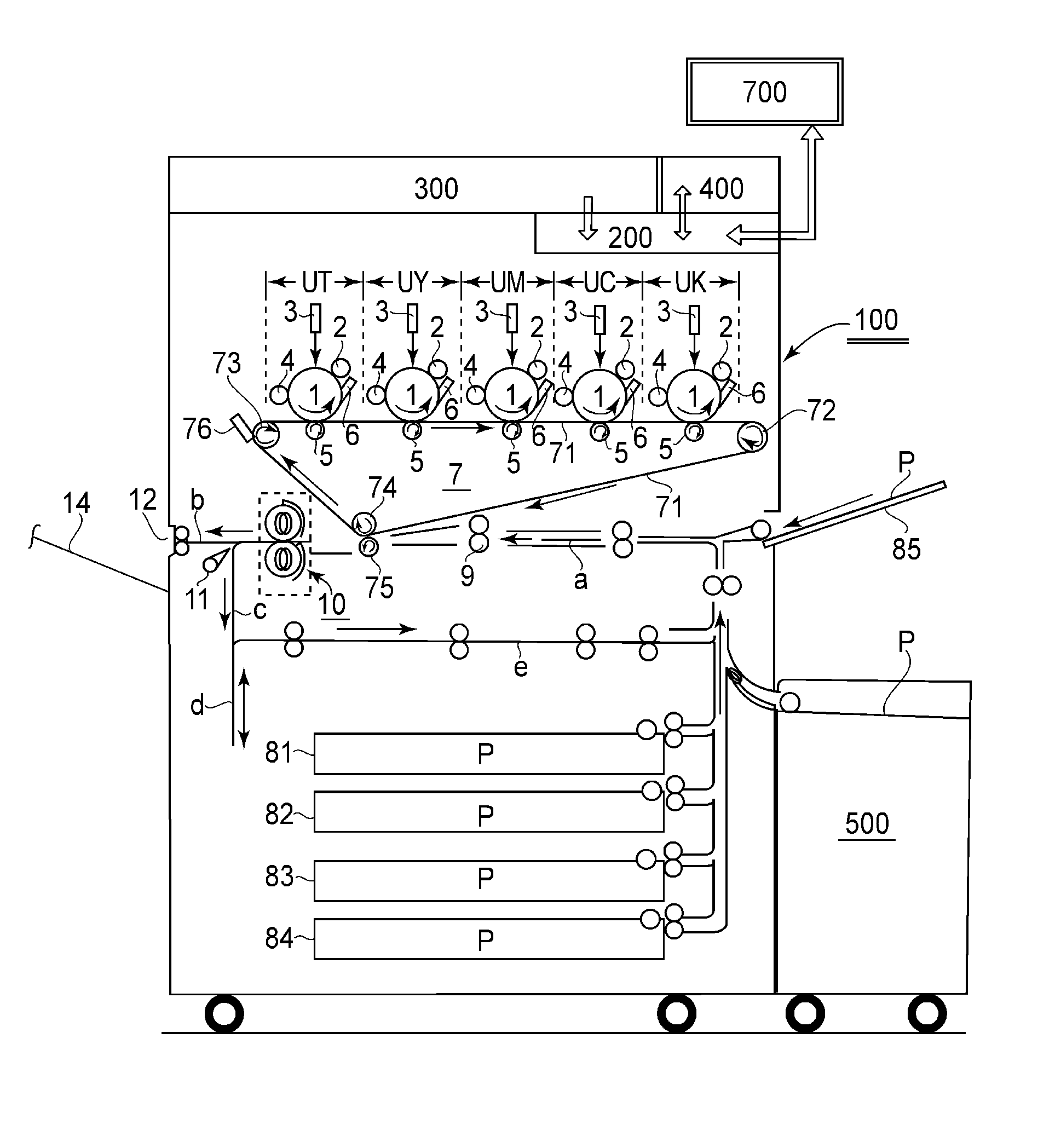
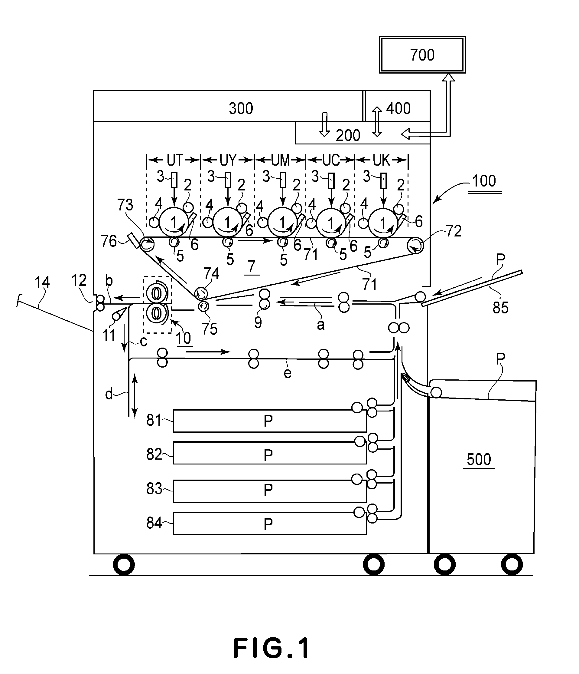
[0032]FIG. 1 is a schematic view of an image forming apparatus to which the present invention is applied. This image forming apparatus 100 is full-color electrophotographic image forming apparatus at a tandem (in-line) type, an intermediary transfer type, and an oil-less fixing type, and is a multi-function machine having a copying machine function, a printer function and a facsimile function. The apparatus 100 includes a control device (controller) 200, an image reading device (image scanner) 300 and an operating portion 400. Further, to the apparatus 100, a large-volume sheet feeding deck 500 as an optional device to be retrofitted is attached in combination.

[0033]The control device 200 is constituted by a central processing unit (CPU) or the like and is a control circuit portion as a control means for integrally controlling an image forming system including various process equipment and devices which relative to image ...

embodiment 2

[Embodiment 2]

[0078]FIG. 6 is a schematic structural view of an image forming apparatus 100 in this embodiment. This apparatus 100 includes a glossing unit 600 as a retrofitted optional device disposed on an image formed product discharge opening 12 side in combination with the main assembly thereof. Thus, the image forming apparatus 100 is configured to further process of the image formed product in the “whole coating” mode so as to become the image formed product having photograph-like gloss. The constitution and operation of the apparatus 100 except the glossing unit 600 are similar to those in Embodiment 1, thus being omitted from redundant description.

[0079]The recording material P which has been subjected to the image formation in the apparatus 100 is introduced from the discharge opening 12 into the unit 600. In the case where the photograph-like gloss mode is not selected, the recording material P is changed in path toward a conveying path f by a first turning attitude of a ...

embodiment 3

[Embodiment 3]

[0102]FIG. 9A is a schematic view of an image forming apparatus 100A in this embodiment. This apparatus 100A is an apparatus (machine for clear (transparent)) for dedicatedly forming the transparent toner image on the recording material P. The constitution of the first image forming portion UT is the same electrophotographic process mechanism as that of the first image forming portion UT for forming the transparent toner image in the apparatus 100 (FIG. 1) in Embodiment 1. Also the fixing device 10 is the heating roller fixing device of the oil-less fixing type similar to that in the apparatus 100 in Embodiment 1. In addition, other constituent members or portions common to the image forming apparatus 100 in Embodiment 1 are represented by the same reference numerals or symbols and will be omitted from redundant description. FIGS. 9B, 9C and 9D are schematic views of display screens of the operating portion 400, and FIG. 10 is a flowchart of the image forming operation...


PUM


Abstract

An image forming apparatus includes a selector for selecting a first mode in which a transparent toner image is partly formed on a surface of a recording material and a second mode in which the transparent toner image is formed so that whole surface of the recording material is coated with a transparent toner; and a controller for controlling execution so that execution of the first and second image forming modes are permitted when information indicates that the recording material has not been subjected to image formation before the recording material is placed to a placing portion and so that execution of the second mode is permitted but execution of the first mode is forbidden when the information indicates that the recording material has already been subjected to image formation before the recording material is placed to the placing portion.

Description

FIELD OF THE INVENTION AND RELATED ART[0001]The present invention relates to an image forming apparatus for forming an image with transparent toner.[0002]In the image forming apparatus using an electrophotographic method, as one of factors for improving image quality, impartation of gloss representation and utilization of a characteristic have been conventionally required.[0003]Specifically, a portion with low gloss and a portion with high gloss are co-present on a surface of an output product (image formed product), or a whole image surface of the output product is uniformly finished to high gloss, medium gloss, low gloss or the like. For example, uses such that an image constituting character information is made legible by lowering the gloss, that a gradation image such as a photograph or an illustration is improved in appearance by increasing the gloss, and that the gradation image is partly increased in gloss to realize emphasized representation would be considered. Further, use...

Claims


Application Information

Patent Timeline
Patent Type & Authority Patents(United States)
IPC IPC(8): G03G15/00
CPCG03G15/5062G03G15/6585G03G2215/00805G03G2215/2074G03G2215/209G03G2215/0129
Inventor SHIOZAWA, MOTOHIDE
Owner CANON KK
Why Eureka
Try Eureka