Image forming apparatus having variable potential setting

a technology of potential setting and forming apparatus, which is applied in the direction of electrographic process apparatus, corona discharge, instruments, etc., can solve the problems of color stability impairment, increased cost, image defect due to electric discharge, etc., and achieve the effect of reducing the degree of an occurren

Inactive Publication Date: 2015-02-17
CANON KK
View PDF21 Cites 1 Cited by
  • Summary
  • Abstract
  • Description
  • Claims
  • Application Information

AI Technical Summary

Benefits of technology

[0011]A principal object of the present invention is to provide an image forming apparatus capable of reducing a degree of an occurrence of improper transfer or image defect due to abnormal electric discharge, in which commonalty of a transfer power source is realized.
[0012]Another object of the present invention is to provide an image forming apparatus, in which commonality of the transfer power source is realized, capable of reducing the degree of the occurrence of the improper transfer or the image defect due to the abnormal electric discharge by passing an optimum current through each of a first transfer means and a second transfer means even in the case where a resistance value or the like is different between the first transfer means and the second transfer means.

Problems solved by technology

Particularly, in the case of the full-color image forming apparatus, due to the lowering in transfer property, there is a possibility that color stability is impaired between an initial state and a state of image formation on a large number of sheets.
Further, when a voltage of a value higher than the optimum voltage value is applied, abnormal electric discharge occurs at the transfer portion, so that there is a possibility that image defect due to the electric discharge occurs.
Therefore, a plurality of power sources are required, so that a cost is increased.
As a result, at the station where the output current value is outside of a proper range, there is a possibility of an occurrence of improper transfer or image defect due to abnormal electric discharge.

Method used


Image

  • Image forming apparatus having variable potential setting
  • Image forming apparatus having variable potential setting
  • Image forming apparatus having variable potential setting

Examples


Embodiment Construction

[0020]Embodiments of the present invention will be described with reference to FIGS. 1 to 5.

[Image Forming Apparatus]

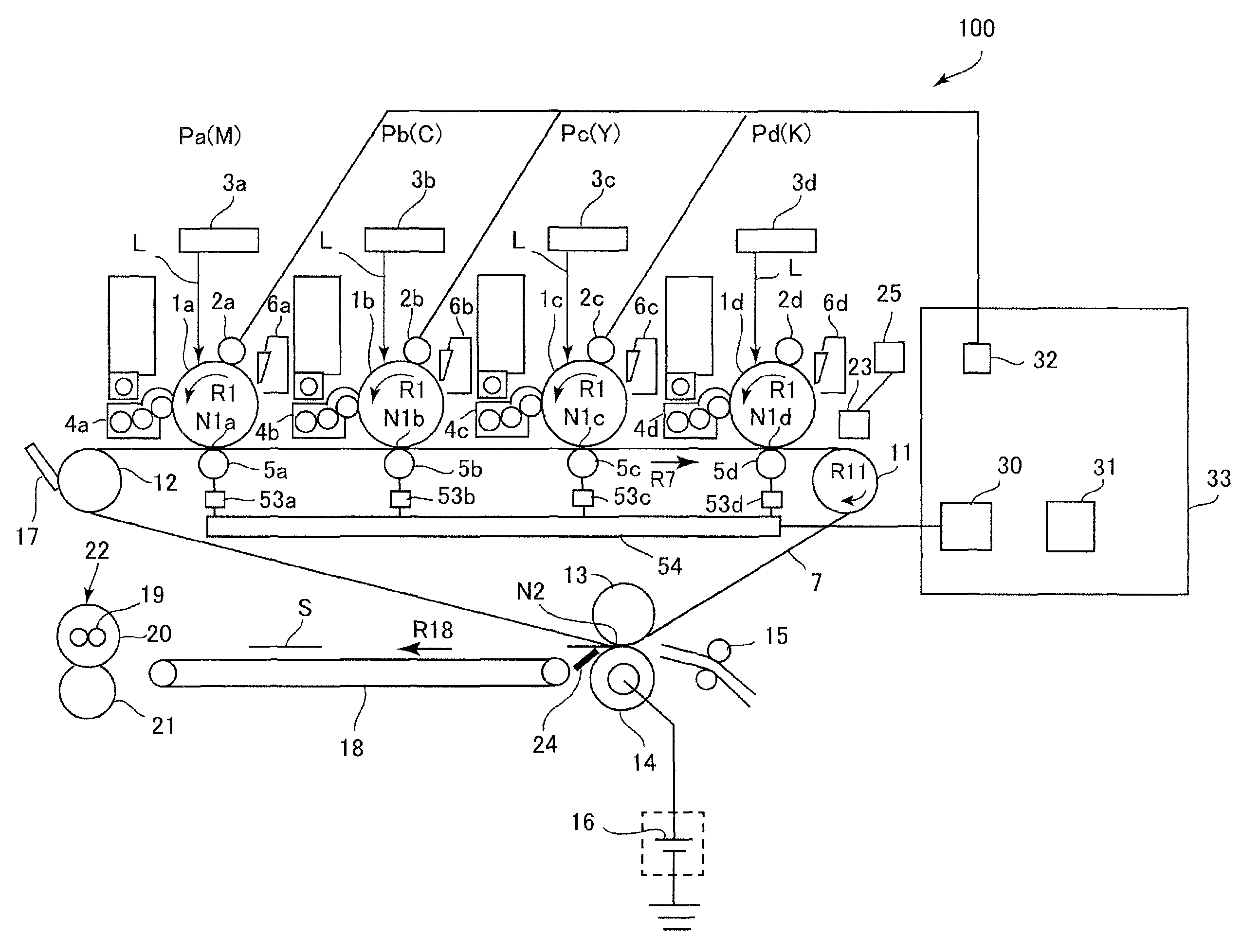
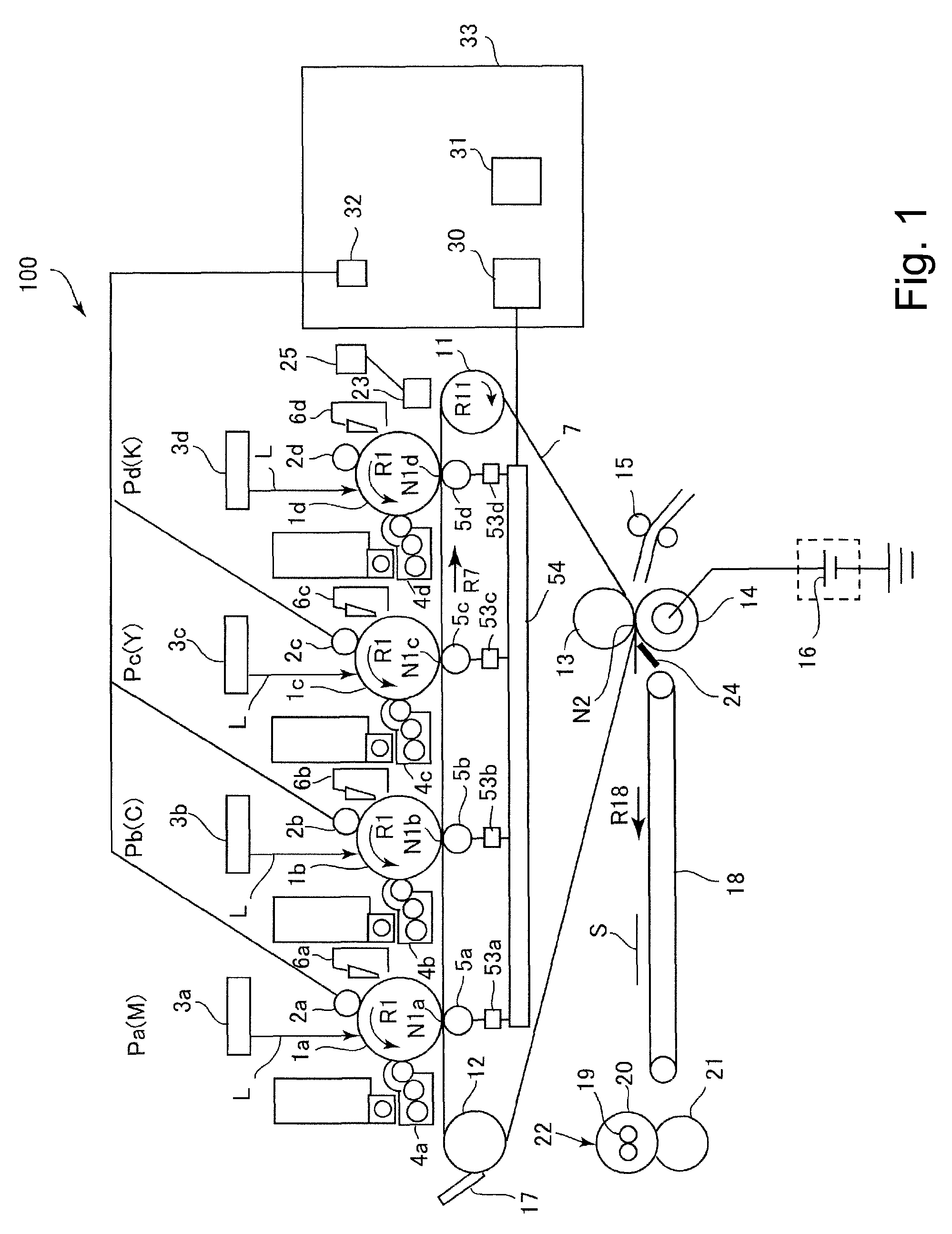
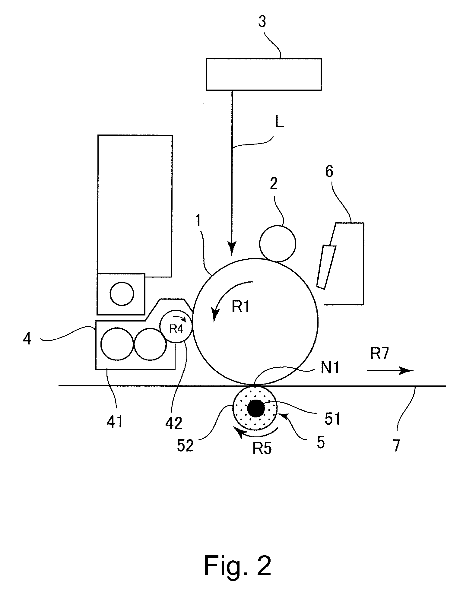
[0021]First, an image forming apparatus in an embodiment of the present invention will be described with reference to FIGS. 1 and 2. An image forming apparatus 100 is a full-color laser printer or a tandem type in which a plurality of image forming portions Pa, Pb, Pc and Pd for magenta (M), cyan (C), yellow (Y) and black (K), respectively are provided along an intermediary transfer belt 7 as a transfer material. In this embodiment, any combination of two of all the image forming portions Pa, Pb, Pc and Pc provides a relationship between a first image forming portion and a second image forming portion.

[0022]At the image forming portions Pa, Pb, Pc and Pd, toner images of magenta, cyan, yellow and black, respectively, are formed. The respective image forming portions have the same constitution except that the colors of the toners used in developing devices 4a, 4b, 4c a...


PUM


Abstract

An image forming apparatus includes a first image forming portion including a first photosensitive member, a first charging member to electrically charge the first photosensitive member, and a first exposure member to expose to light the charged first photosensitive member to form an electrostatic latent image, and a second image forming portion including a second photosensitive member, a second charging member to electrically charge the second photosensitive member, and a second exposure member to expose to light the charged second photosensitive member to form an electrostatic latent image. In addition, a power source applies a common voltage to a first transfer portion and a second transfer portion, and a setting portion variably sets, for a period in which a transfer operation is performed, a potential of the exposed portion or the charged portion of the first photosensitive member and a potential of the exposed portion or the charged portion of the second photosensitive member on the basis of a plurality of currents passing through the first transfer portion and a plurality of currents passing through the second transfer portion, respectively, when the plurality of common voltages are applied to the first transfer portion and the second transfer portion in a period other than the period in which the transfer operation is performed.

Description

FIELD OF THE INVENTION AND RELATED ART[0001]The present invention relates to an image forming apparatus of an electrophotographic type, such as a copying machine, a printer, a facsimile machine, or a multi-function machine of these machines, in which a plurality of image forming portions are provided.[0002]As the image forming apparatus of the electrophotographic type, a structure in which an intended image is visualized as a toner image by subjecting a surface of a photosensitive drum to an image forming process including steps of charging, exposure, development and the like and then the toner image is transferred onto a transfer material in a transfer step has been known.[0003]Further, a structure in which a full-color image can be obtained by superposing toner images of a plurality of colors has also been conventionally known. As this structure, there is, e.g., a structure in which a plurality of image forming portions (image forming stations) are provided and toner images formed...

Claims


Application Information

Patent Timeline
Patent Type & Authority Patents(United States)
IPC IPC(8): G03G15/02G03G15/043
CPCG03G15/0131G03G15/0189G03G15/043G03G15/1675G03G2215/0129
Inventor KOJIMA, ETSUJI
Owner CANON KK
Why Eureka
Try Eureka