Shipping container

a shipping container and container technology, applied in the field of reusable shipping containers, can solve the problems of shipping containers incurring shipping containers tend to incur significant damage to the fork strap and the feet, and the fork to impact one or more of the feet with significant force, so as to achieve easy dunnage acceptance, reduce the capacity of the container, and add additional weight and cost

Active Publication Date: 2013-05-07
MACROPLASTICS
View PDF57 Cites 25 Cited by
  • Summary
  • Abstract
  • Description
  • Claims
  • Application Information

AI Technical Summary

Benefits of technology

[0018]The present invention relates to reusable shipping containers and in particular to reusable containers that utilize a replaceable fork strap assembly where the exposed portion of the feet of the container is integral to the fork strap unit rather than the base of the container. The invention further relates to a container in which the fork straps in one direction can be formed at the upper portion of the feet to enable use of the container with a pallet jack without lessening the capacity of the container or adding additional weight and cost to the container to maintain the same capacity. The invention further relates to a container that is adapted to easily accept dunnage required for the protection and organization of material being shipped in the container.

Problems solved by technology

These forklifts drive at considerable speed and can be difficult to handle.
As a result these shipping containers tend to incur significant damage to the fork strap and the feet.
This damage occurs when the operator of a forklift poorly aligns the forks with the fork slots causing the fork to impact one or more of the feet with significant force.
The feet of such containers also can experience damage when the operator of a lift uses the edges of the forks to slide a container sideways on the floor without lifting the container.
And the sides of the feet are also subject to being sliced by the tips of the forks when the operator of a lift executes a quick turn when the forks are not clear of the container.
Often the damage inflicted by a fork truck can be catastrophic and can render the container unusable, sometimes breaking off large pieces of the base.
When this occurs, one must either replace the entire base of the container at a significant cost or purchase a completely new container.
Another type of damage that is very common to these types of containers is that one or more fork straps will break due to abuse.
Thus, when the fork strap breaks it is necessary to replace the entire base because it is not possible to replace or repair the strap, thereby causing the owner of the container considerable expense.
The problem with this design is that if a foot is damaged, the fork straps, or fork strap assembly, can no longer be replaced.
Once one or more feet of a container sustain sufficient damage or one or more fork straps are broken, the container can be rendered unusable.
In practice, however, the entire container is frequently scrapped because the cost of the labor involved in disassembling the damaged container and assembling the old sides to a new base outweighs the cost of a new container.
Some known designs provide some protection to the exterior sides of the feet on the perimeter of the container, but these designs do not address the full scope of the problem because no protection is provided for the other sides of the perimeter feet or the centrally located feet.
In addition, the feet and the protection extend down from the base, meaning that there is no means of replacing a damaged foot.
These designs also provide only a single layer of protection to the exterior side of the feet that is easily punctured by a direct hit from a fork.
In such cases, the fork straps make it difficult, if not impossible, to position the pallet jack under the base to lift the container.
This results in the lessening of the capacity of the container due to the elimination of a plurality of fork straps that stiffen the container.
In some cases, the base of the container will be reinforced with metal plates or other material to maintain the capacity of the container, but this increases the weight of the container and may reduce the number of containers that can be shipped in a single truck due to weight restrictions and will result in increased consumption of fuel.
Such reinforcement is also costly because it adds additional material and labor to the cost of the container.
Another issue with known containers is the lack of a standard manner of handling dunnage.
Frequently material shipped in such containers requires a great deal of dunnage to prevent the material from being damage.
Known methods of addressing the dunnage problem include the use of disposable dunnage or expensive retrofitting of containers to accept reusable dunnage.

Method used


Image

  • Shipping container
  • Shipping container
  • Shipping container

Examples


Embodiment Construction

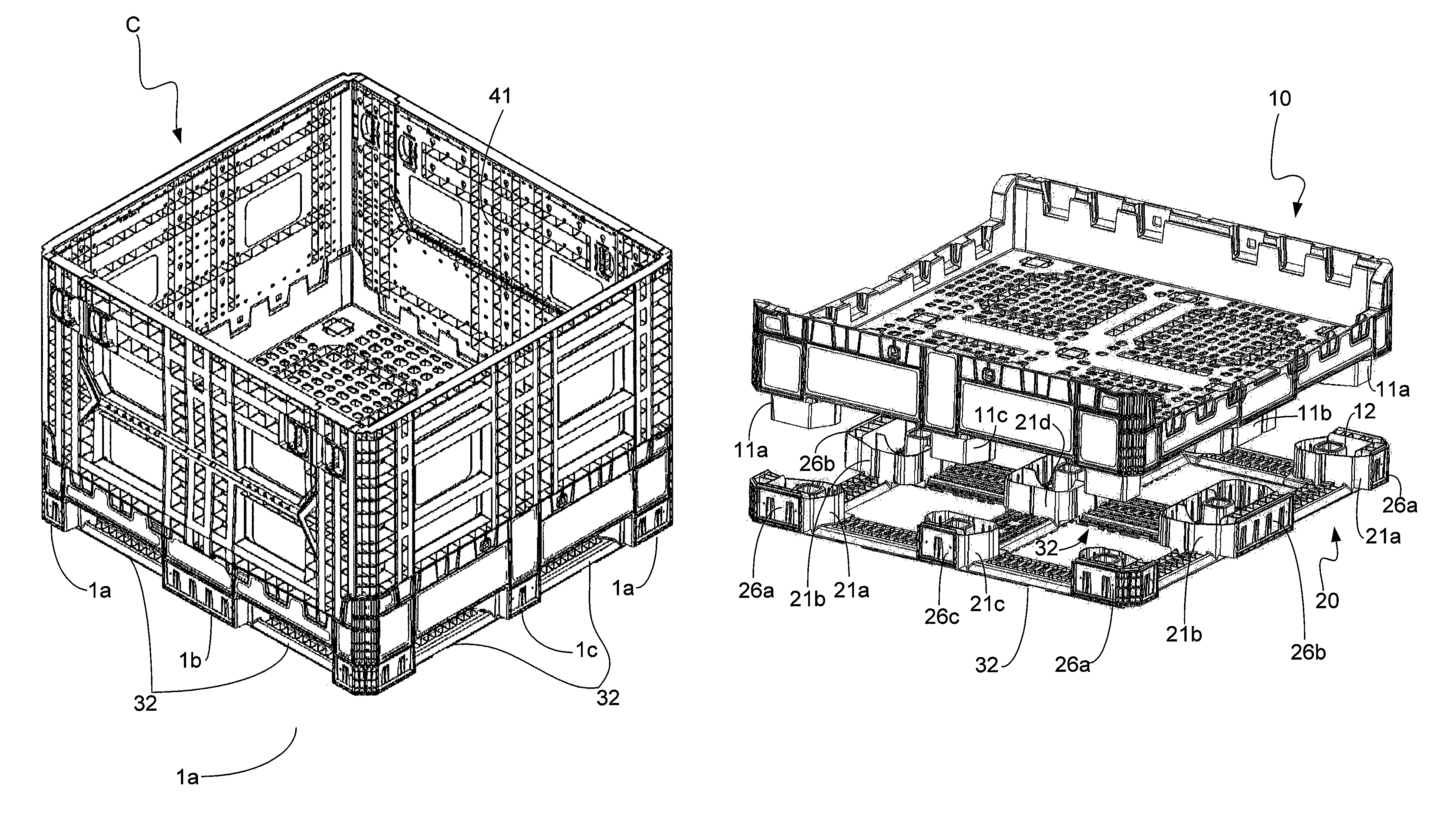
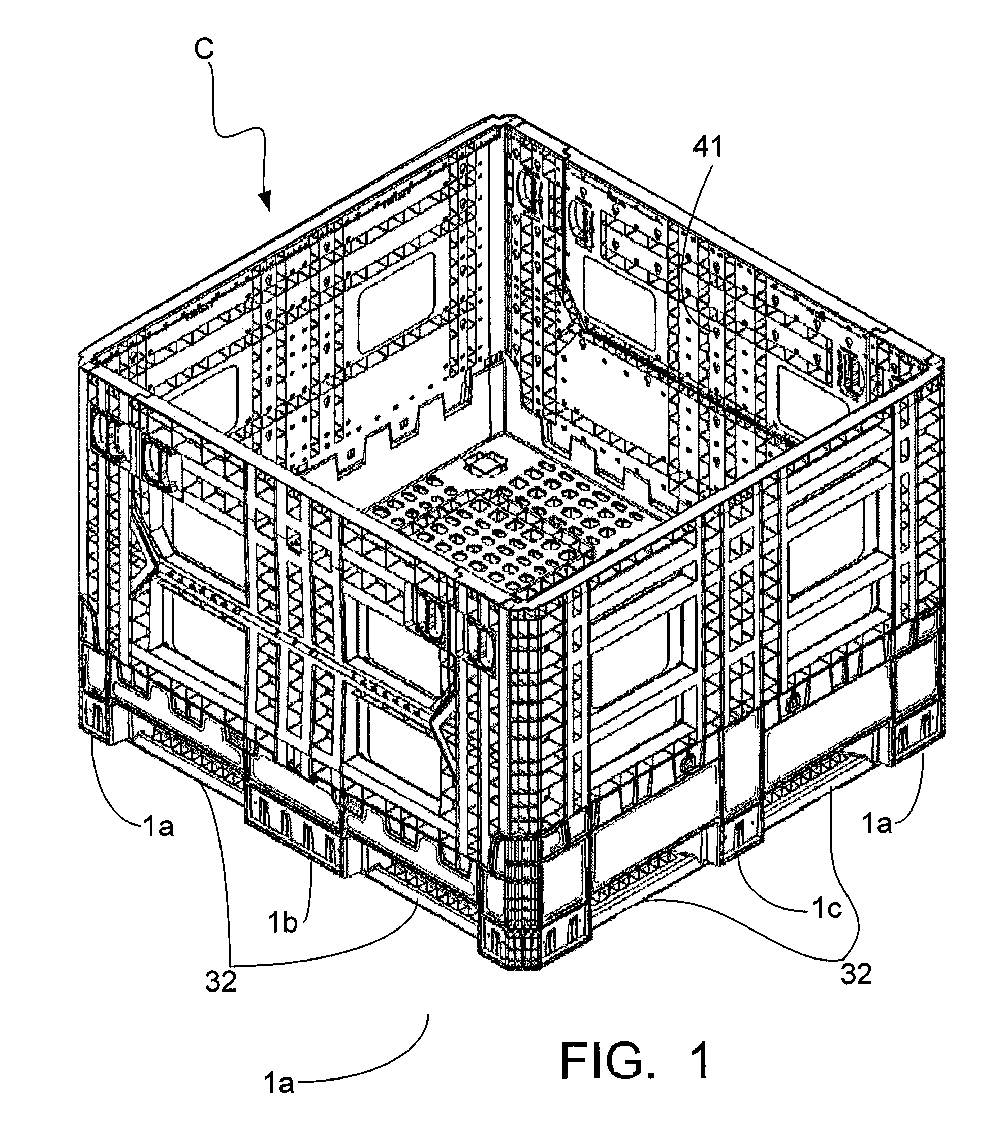
[0036]The present invention is a novel shipping container C that addresses the problems described above. In known containers, post-like “feet” extend downward from the base to provide a gap under the base to allow the forks of a fork truck to slide under the base. The fork strap is then either integrally formed between the feet in a known pattern or snapped into the feet. This results in the feet being exposed to direct hits from the forks of the fork truck, and when they are damaged, causing the owner of the container to either have to replace the entire base, including the base portion, or to scrap the container. Considering the cost of disassembling the sides of the container from the base, containers with damaged feet are more frequently scrapped than repaired.

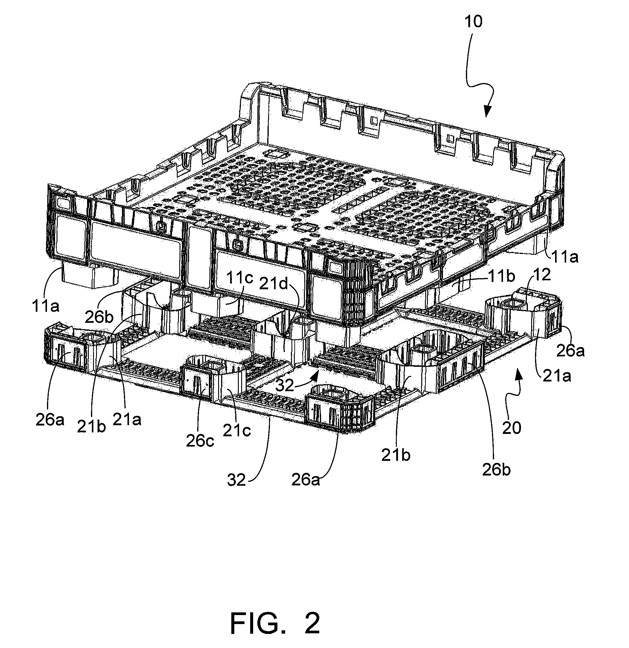
[0037]This invention includes a novel bottom unit design that comprises base 10 and separate fork strap unit 20 with fork strap unit 20 being easily replaceable and much more durable in foot portions 1 than known container...


PUM


Abstract

A reusable shipping container adapted to resist damage to the feet of the container and to allow the fork straps to be replaced if the fork straps or the feet are damage. The container can also easily be adapted to accommodate the use of pallet jacks without reducing the capacity of the container or increasing the weight of the container. The container is also adapted to easily receive dunnage required to protect the material being shipped in the container.

Description

CROSS-REFERENCE TO RELATED APPLICATIONS[0001]This is a U.S. national stage application of PCT / US09 / 49665 filed Jul. 7, 2009, which claims priority of U.S. Provisional Application No. 61 / 077,875, filed Jul. 3, 2008, which is hereby incorporated herein by reference.STATEMENT REGARDING FEDERALLY SPONSORED RESEARCH OR DEVELOPMENT[0002]Not applicableREFERENCE TO A “MICROFICHE APPENDIX”[0003]Not applicableBACKGROUND OF THE INVENTION[0004]1. Field of the Invention[0005]The present invention generally relates to shipping containers, and more specifically to reusable shipping containers that are designed to be moved via forks attached to a lift vehicle or by a pallet jack or similar apparatus.[0006]2. General Background of the Invention[0007]Various types of reusable containers have long been used in the field of material handling. These containers generally include a base that forms the bottom of the container, a forkstrap assembly that may or may not be integral to the base, and sidewalls ...

Claims


Application Information

Patent Timeline
Patent Type & Authority Patents(United States)
IPC IPC(8): B65D19/00B65D19/12B65D8/14
CPCB65D19/06B65D2519/009B65D2519/00069B65D2519/00174B65D2519/00273B65D2519/00288B65D2519/00308B65D2519/00318B65D2519/00323B65D2519/00348B65D2519/00358B65D2519/00363B65D2519/00407B65D2519/00412B65D2519/00417B65D2519/00422B65D2519/00502B65D2519/00517B65D2519/00567B65D2519/00651B65D2519/00975B65D2519/0099B65D2519/00034Y02W30/80
Inventor MITCHELL, JEFFREY W.TURNER, TODD T.
Owner MACROPLASTICS
Why Eureka
Try Eureka