
Encapsulated fastener assembly

a technology of fasteners and assemblies, applied in the direction of threaded fasteners, fastening means, domestic applications, etc., can solve the problems of increasing parts costs, increasing labor time and cost, and posing problems for existing fasteners

Active Publication Date: 2013-05-07
ENGINEERED COMPONENTS COMPANY
View PDF16 Cites 31 Cited by
  • Summary
  • Abstract
  • Description
  • Claims
  • Application Information

AI Technical Summary

Benefits of technology

The present invention provides a fastener assembly for securing two materials together, including an externally threaded screw and an internally threaded nut. The combined thickness of the two materials is less than the length of the screw inserted into them. The screw has ridges on its shank, and the nut has a blind hole with internally threaded walls. An encapsulating plastic layer covers the head of the nut and surrounds a portion of the screw shank. The plastic layer has a thickness that is equal to or greater than the difference between the screw length and the material thickness. The technical effects of this invention include improved fastening speed, secure and strong fastening, and durability.

Problems solved by technology

In some uses of encapsulated fastener assemblies, such as in the construction of wall panels for truck bodies, stronger, lighter and thinner materials are being used which have been posing problems for existing fasteners.
As the panels and extrusions to be joined together become thinner, their combined thickness becomes smaller than the length of the screw of the fastener assembly, which has a predetermined minimum length due to fabrication limitations.
When this occurs, the screw cannot be tightened completely into the nut because the screw bottoms out on the bottom of the blind hole in the nut before the head of the nut and the head of the screw tightly clamp the plies of the panels together.
A solution of using washers or other spacers under the head of the nut to hold the head of the nut away from the surface that the screw protrudes through not only increases the parts costs, but also the labor time and cost for assembly.
Further, the use of washers or spacers can reduce the effectiveness of the liquid seal provided by the encapsulating head of the nut.

Method used


Image

  • Encapsulated fastener assembly
  • Encapsulated fastener assembly
  • Encapsulated fastener assembly

Examples


Embodiment Construction

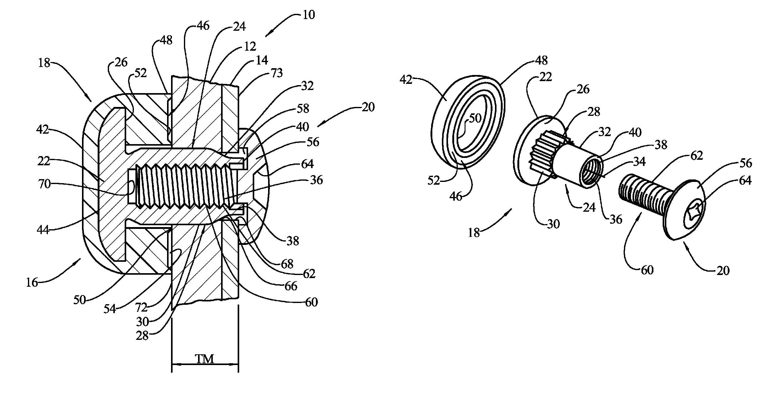
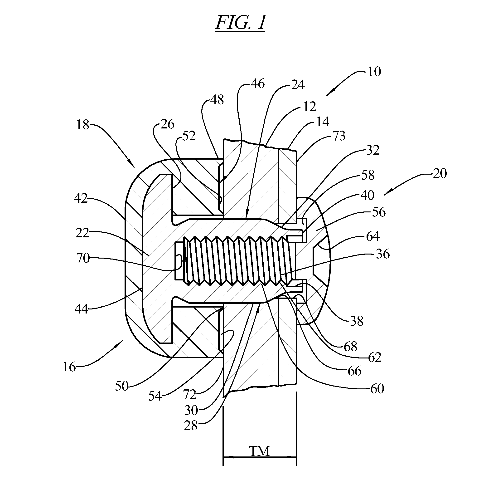
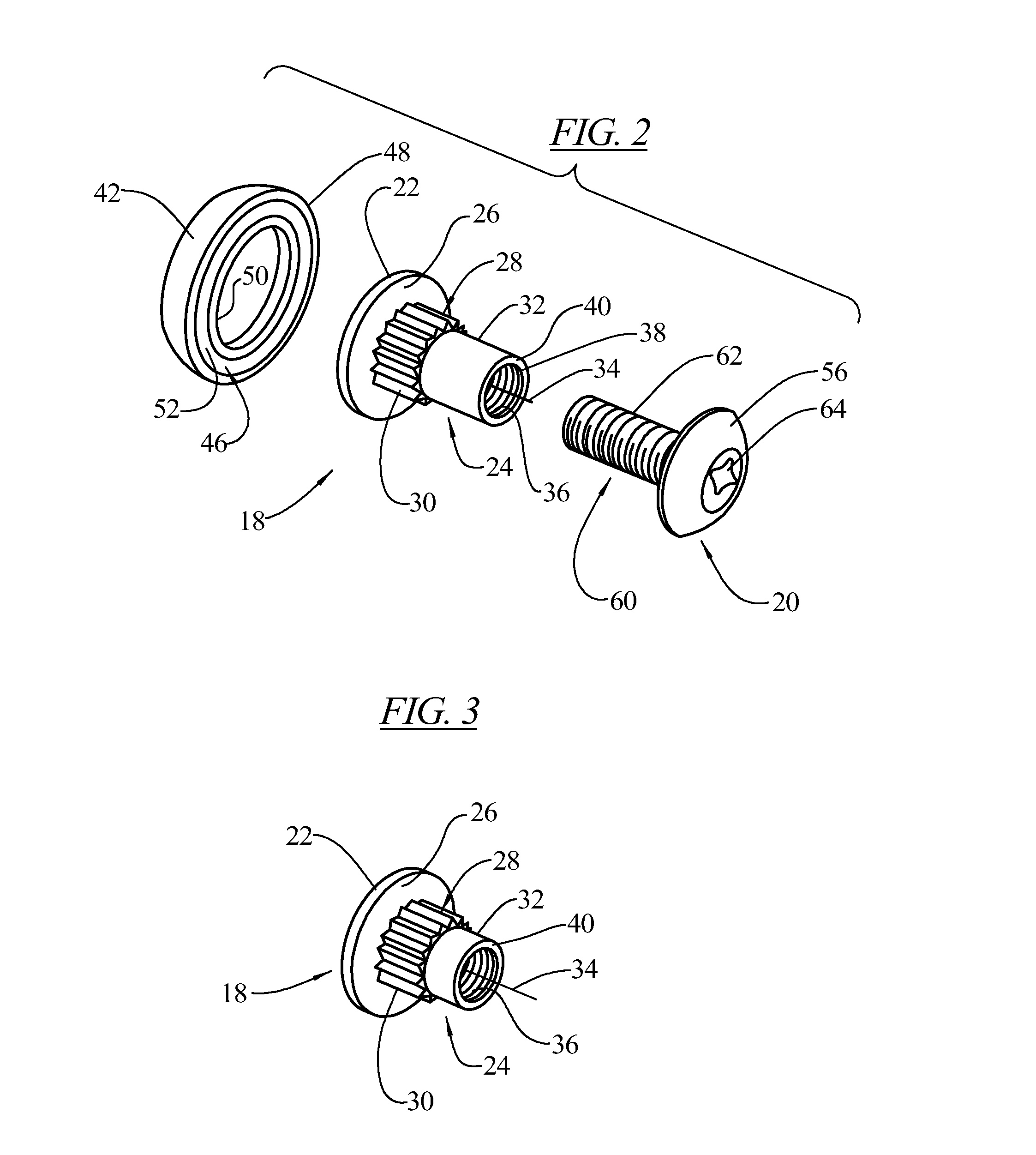
[0022]FIG. 1 illustrates a portion of a structure 10 (such as a container, portable shelter or truck body) in which a material forming a first structural component 12 such as a wall panel is secured to a second structural component 14 such as an extrusion by means of a plurality of fastener assemblies 16. Although only two layers of structural components are shown, any number of two or greater structural components may be secured together with the fastener assembly 16 of the present invention.

[0023]As shown in FIGS. 1 and 2, each of the fastener assemblies 16 includes a first fastener member 18 and a second fastener member 20. The first fastener member 18 may be in the form of a T-nut which includes a generally disc-shaped head portion 22. A generally cylindrical shank portion or post 24 is secured to, and extends from, an underside 26 of the head portion 22. The shank portion 24 may be provided with an anti-rotation structure 28 in the form of a plurality of longitudinal ridges 30....


PUM


Abstract

A fastener assembly including an internally threaded nut and an externally threaded screw for securing at least two materials together. A combined thickness TM of the materials is less than a length SL of the screw inserted into the materials. The nut includes a head, a shank extending from the head, and an internally threaded bore extending into the shank. The screw includes a head and an externally threaded shank adapted to threadingly engage the internally threaded bore of the nut. An encapsulating plastic layer covers the head of the nut. The plastic layer extends under and covers a bottom surface of the head. The plastic layer has a thickness TE below the bottom surface of the head which is equal to or greater than a difference between the screw length SL and the material thickness TM.

Description

BACKGROUND OF THE INVENTION[0001]The present invention relates to a fastener assembly, and in particular to a fastener assembly including a nut with an enlarged head and an internally threaded shank with an encapsulating plastic layer protecting the enlarged head of the nut. An externally threaded screw is received in the internally threaded shank of the nut.[0002]It is known in the art to encapsulate fasteners with some type of a plastic covering. Such covered heads are disclosed in U.S. Pat. Nos. 73,088; 563,969; 1,941,175; 1,867,354; 3,470,787; 3,693,495 and 4,293,243. Other types of covered heads are disclosed in U.S. Pat. Nos. 3,134,290; 4,316,690; 4,373,842; and 4,482,278. An encapsulated head, barbed shank fastener is disclosed in U.S. Pat. No. 5,244,326, the disclosure of which is incorporated herein in its entirety. A closed-end ridged neck threaded fastener is disclosed in U.S. Pat. No. 5,244,326, the disclosure of which is incorporated herein in its entirety.[0003]Fastene...

Claims


Application Information

Patent Timeline
Patent Type & Authority Patents(United States)
IPC IPC(8): F16B21/00
CPCF16B37/14F16B37/145
Inventor HENRIKSEN, JR., ARNE
Owner ENGINEERED COMPONENTS COMPANY
Learn More