Hammering tool with buffer design

a buffer design and hammering tool technology, applied in the field of hand tools, can solve the problems of repeated hand injury and hand injury, and achieve the effect of improving the safety of users

Active Publication Date: 2013-05-14
CHEN KUAN WEI
View PDF4 Cites 4 Cited by
  • Summary
  • Abstract
  • Description
  • Claims
  • Application Information

AI Technical Summary

Benefits of technology

[0006]It is therefore a primary object of the present invention to provide a hammering tool with buffer design. When using the hammering tool to hammer a work piece, the hammering tool is able to buffer the strong reaction force and provide anti-shock effect for a user's hand to avoid occupational disease of repeated injury.

Problems solved by technology

After using the hammer to hammer the work piece for a period of time, such shocking force may cause an occupational disease of repeated injury to the user's hand.

Method used


Image

  • Hammering tool with buffer design
  • Hammering tool with buffer design
  • Hammering tool with buffer design

Examples


first embodiment

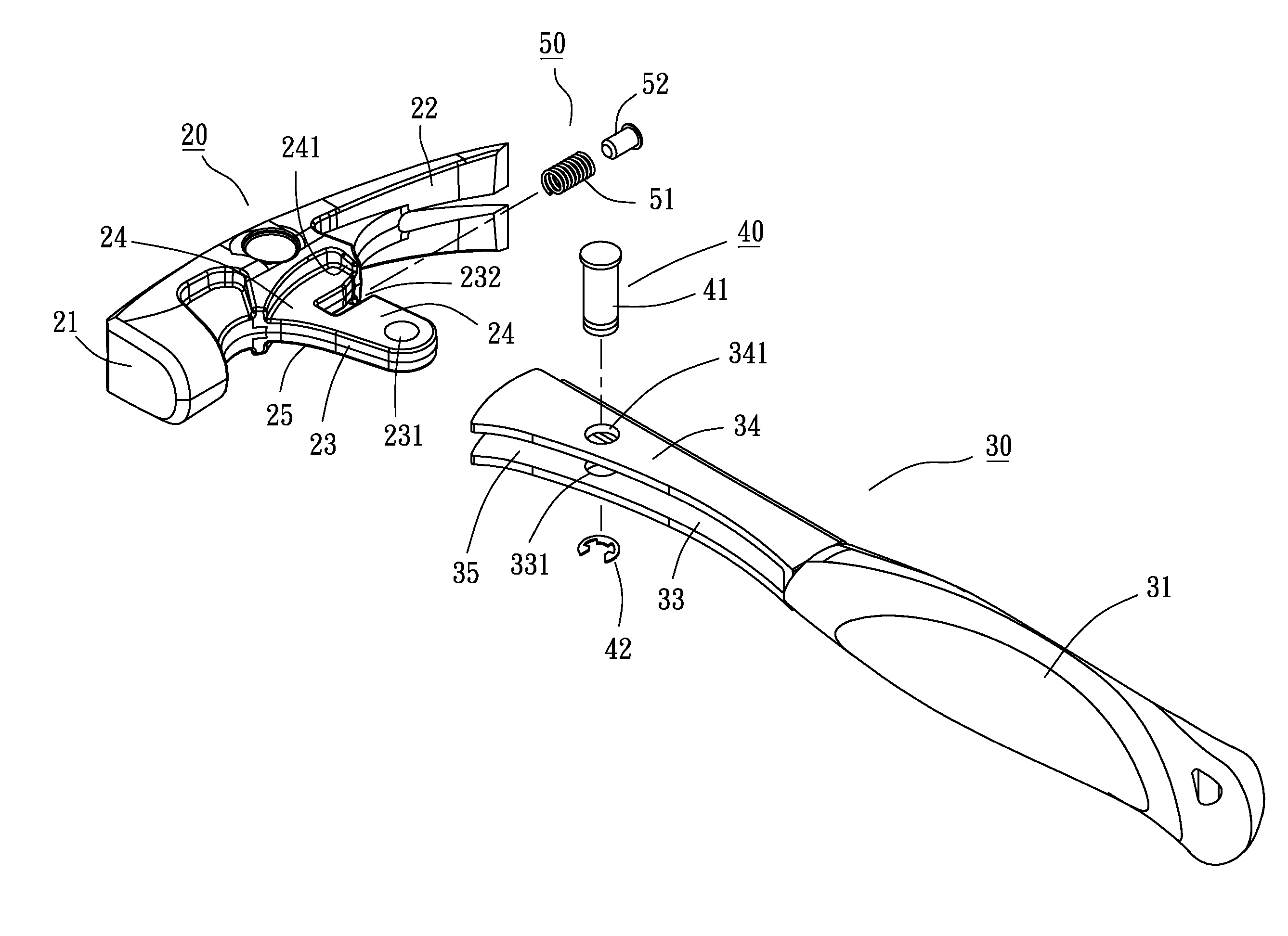
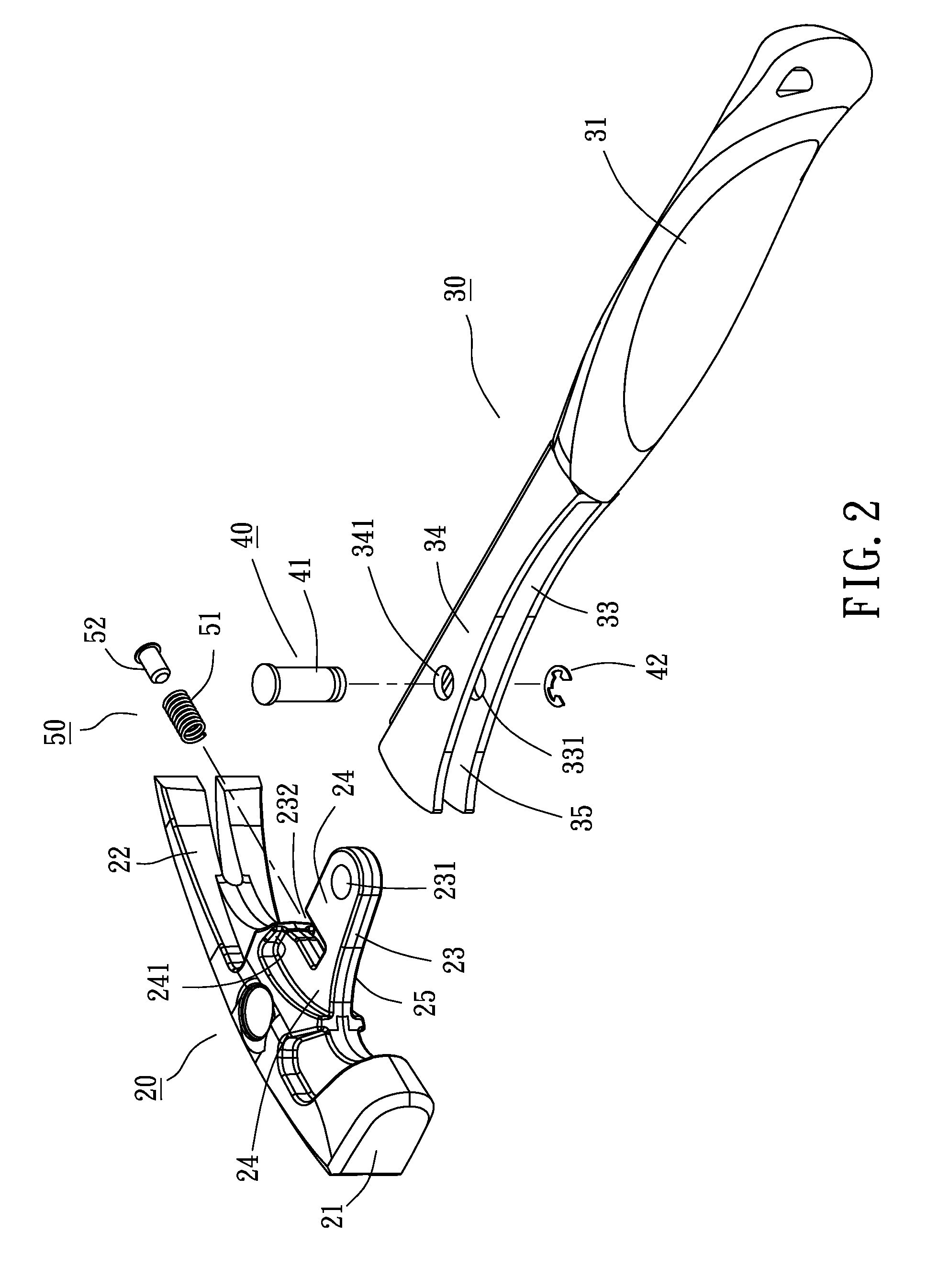
[0022]Please refer to FIGS. 2 to 11. the hammering tool with buffer design of the present invention includes a hammering member 20 made of steel or other metal material. The hammering member 20 has a hammering section 21 and a nail pulling section 22 on a right side of the hammering section 21. A protrusion block section 23 extends from a lower side of the hammering member 20. A top section of the protrusion block section 23 is formed with a first depression 24. A bottom section of the protrusion block section 23 is formed with a second depression 25 corresponding to the first depression 24. A first stop section 241 is disposed on an upper right side of the first depression 24. The second depression 25 is provided with a second stop section 251 opposite to the first stop section 241. A lower end of the protrusion block section 23 is formed with a first through hole 231. A right side of upper section of the protrusion block section 23 is notched to form a first receiving space 232.

[...

second embodiment

[0029]Please now refer to FIGS. 14 and 15, which show the present invention. The second embodiment is different from the first embodiment in that the hammering member 20 is further formed with a second receiving space 233 under the first receiving space 232 for receiving a second compression spring 60. Such arrangement is applicable to a hammering tool with heavier weight and larger size to provide better anti-shock effect.


PUM


Abstract

A hammering tool with buffer design includes: a hammering member, a protrusion block section extending from a lower side of the hammering member, a right side of upper section of the protrusion block section being notched to form a first receiving space; a handle member having a grip section, a first plate section, a second plate section and a third plate section being disposed at an upper end of the grip section to define a receiving chamber for inserting the protrusion block section therein; a pivot member for pivotally connecting the protrusion block section of the hammering member with the handle member; and a buffer assembly including a first compression spring received in the first receiving space. A right end face of the protrusion block section of the hammering member is spaced from a left face of the first plate section by a predetermined buffering distance.

Description

BACKGROUND OF THE INVENTION[0001]1. Field of the Invention[0002]The present invention relates generally to a hand tool, and more particularly to a hammering tool with buffer design.[0003]2. Description of the Related Art[0004]The conventional hammers are typical hammering tools and are very popularly used to hammer work pieces. FIG. 1 shows a conventional hammer 10, which includes a hammering member 11 and a handle 12. The hammering member 11 is affixed to the handle 12 for hammering a work piece. The handle 12 is for a user to hold and operate the hammer 10.[0005]It is known that when hammering a work piece with the hammer 10, a strong reaction force is applied and transmitted to a user's hand to shock the user's hand. After using the hammer to hammer the work piece for a period of time, such shocking force may cause an occupational disease of repeated injury to the user's hand.SUMMARY OF THE INVENTION[0006]It is therefore a primary object of the present invention to provide a hamm...

Claims


Application Information

Patent Timeline
Patent Type & Authority Patents(United States)
IPC IPC(8): B25D1/00B25D1/02B25D1/06B66F15/00B25C11/00B25D1/16B25D1/12
CPCB25D1/12B25D2250/371
Inventor CHEN, KUAN-WEI
Owner CHEN KUAN WEI
Why Eureka
Try Eureka