Dual lock brake lathe chuck

a technology of double lock and brake rotor, which is applied in the direction of chucks, mechanical devices, manufacturing tools, etc., can solve the problems of obstructing the key lock by the brake rotor, affecting the effective tightening of the brake rotor onto the chuck, and affecting the user's experien

Inactive Publication Date: 2013-05-28
DOLE LONG
View PDF5 Cites 1 Cited by
  • Summary
  • Abstract
  • Description
  • Claims
  • Application Information

AI Technical Summary

Problems solved by technology

However the location of these key holes poses a problem and inconvenience for users.
When a brake rotor is in place on the chuck often times, the brake rotor will obstruct the key lock from accessing the key hole from tightening the chuck.
The placement of the keyholes on the circumference not only hinders the key lock from accessing it, it also makes it hard for the user to effectively tighten a brake rotor onto the chuck.
Unable to effectively tighten a brake rotor onto a chuck, current brake lathe chuck pose a dangerous risk when operating the lathe.

Method used


Image

  • Dual lock brake lathe chuck
  • Dual lock brake lathe chuck
  • Dual lock brake lathe chuck

Examples


Embodiment Construction

[0012]All illustrations of the drawings are for the purpose of describing selected versions of the present invention and are not intended to limit the scope of the present invention.

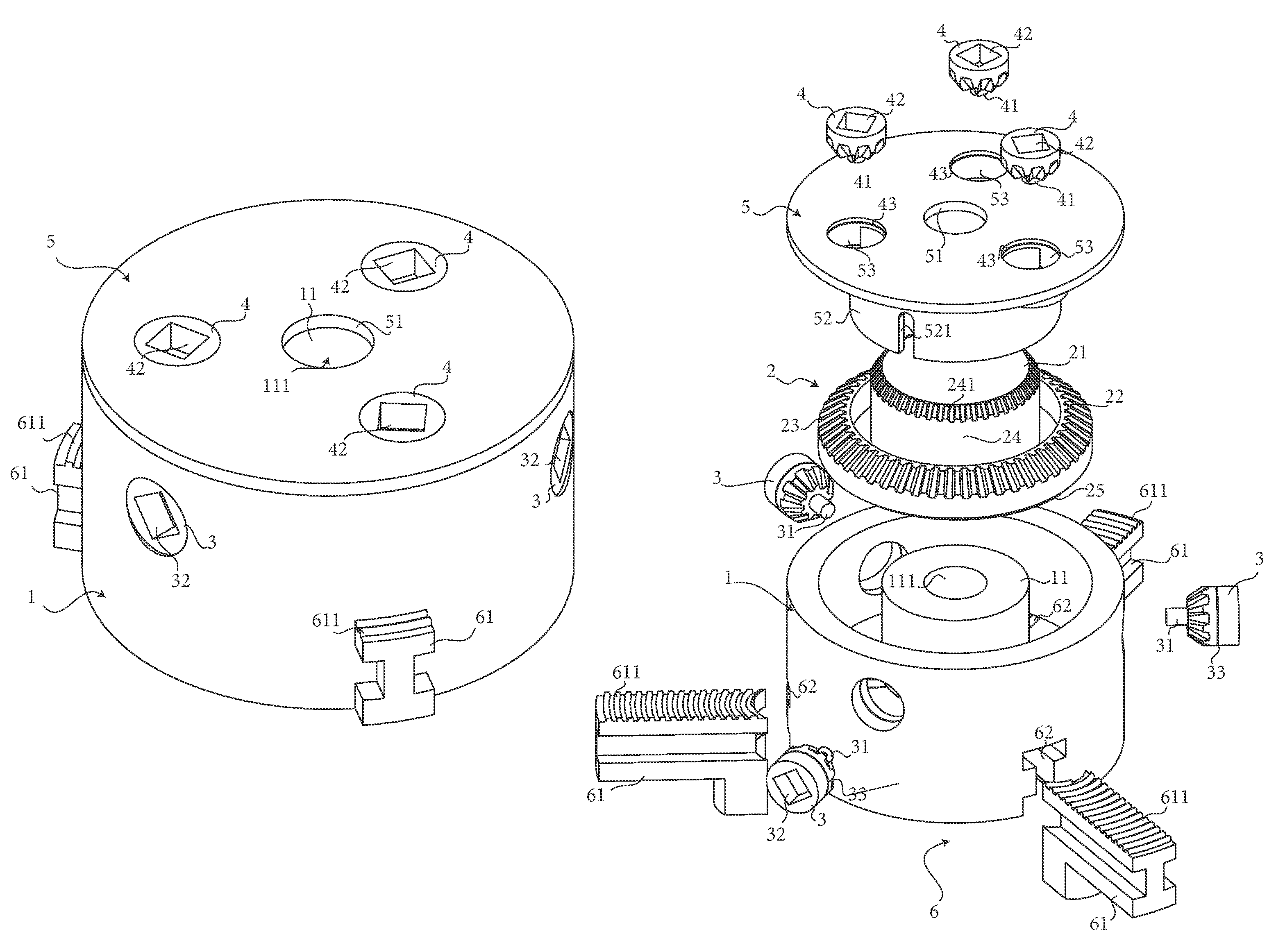
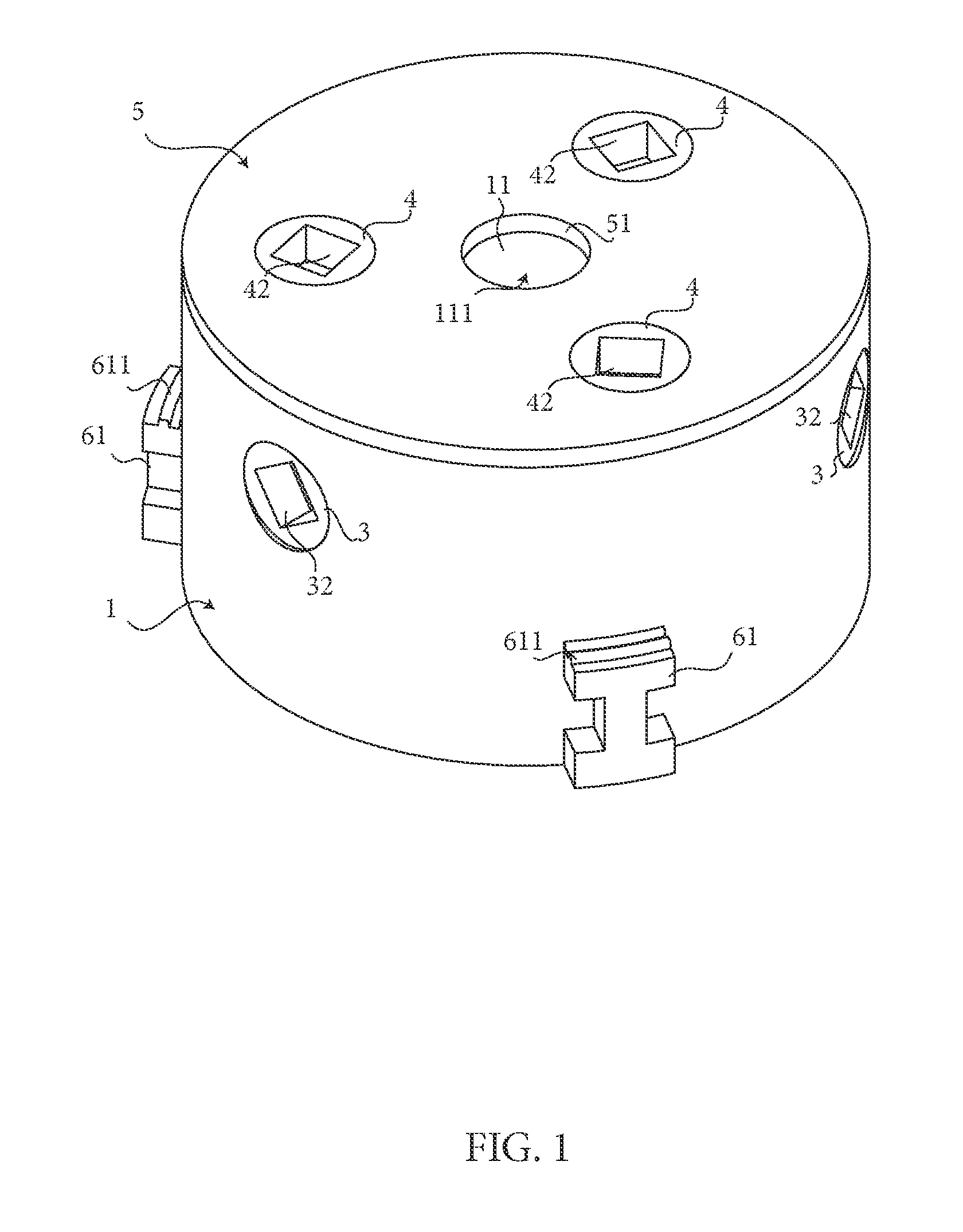
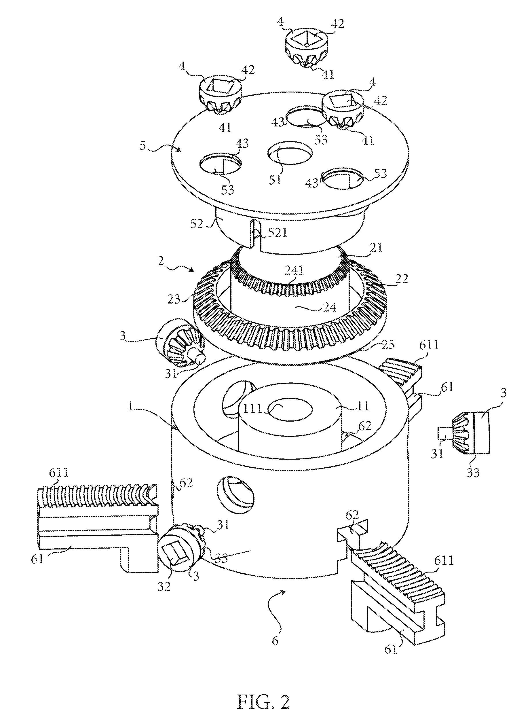
[0013]A dual lock brake lathe chuck comprises of a housing 1, a primary gear 2, at least one primary drive gear 3, at least one secondary drive gear 4, a back plate, and a jaw extension system 6. The primary gear 2 is positioned inside the housing 1 and engages the jaw extension system 6. The primary gear 2 comprises of a primary gear center 21, a primary gear first surface 22, a plurality of primary teeth 23, a primary gear wall 24, and a spiral 25. The primary gear center 21 is a center hole on the primary gear 2 where all other components of the primary gear 2 surround the center hole in radial form. The primary gear wall 24 forms the wall of the primary gear center 21 and is positioned between the primary gear center 21 and the primary gear first surface 22. The primary gear first surface 22 is the s...


PUM


Abstract

A dual lock brake lathe chuck comprises of at least one primary drive gear with keyhole along with at least one secondary drive gear with keyhole. The keyhole is rotated through the side of the chuck whereas the secondary keyhole is rotated through the back of the chuck. Rotation of either the primary keyhole or the secondary keyhole extends a plurality of jaws to secure a brake rotor on a brake lathe. The secondary keyhole positioned on the back of the chuck allows easier access of the keyhole when a brake rotor is attached to the chuck allowing the user to ensure that the brake rotor is securely tightened onto the brake lathe chuck.

Description

[0001]The current application claims a priority to the U.S. Provisional Patent application Ser. No. 61 / 312,338 filed on Mar. 10, 2010.FIELD OF THE INVENTION[0002]The invention relates generally to a device used to hold brake rotors for resurfacing. The objective of the present invention is to allow users to ease the securing process of the rotor to the chuck.BACKGROUND OF THE INVENTION[0003]Brake lathe chucks have a plurality of jaws 61 which can be tightened to secure a brake rotor in place when spinning. To tighten these jaws, a series of gears within the chuck are turned. On a typical chuck, the gears are turned by means of a key lock. These key locks are inserted into a hole on the chuck which will allow the key to access the gears within the chuck for turning. Currently, the brake lathe chucks being sold on the market only offer chucks with key holes located on the circumference of the chuck. However the location of these key holes poses a problem and inconvenience for users. W...

Claims


Application Information

Patent Timeline
Patent Type & Authority Patents(United States)
IPC IPC(8): B23B31/02B23B31/16
CPCB23B31/16004Y10T82/2552Y10T82/26Y10T74/19642
Inventor DOLE, LONG
Owner DOLE LONG
Why Eureka
Try Eureka