Power transmission device for a water pump

a technology of power transmission device and water pump, which is applied in the direction of positive displacement liquid engine, piston pump, interengaging clutch, etc., can solve the problems of poor reliability in the operation of the power transmission device, and achieve the effect of preventing wear and damage of parts, quick and accurate operation

Active Publication Date: 2013-06-11
HANON SYST
View PDF10 Cites 0 Cited by
  • Summary
  • Abstract
  • Description
  • Claims
  • Application Information

AI Technical Summary

Benefits of technology

[0014]Accordingly, the present invention has been made in view of the above-mentioned problems occurring in the prior art, and it is an object of the present invention to provide a power transmission device for a water pump for cooling an automobile engine, wherein power regulation between a disk and a hub in the water pump can be rapidly and accurately performed, while the wearing and damage of the parts can be prevented.

Problems solved by technology

These problems undesirably make the reliability in the operation of the power transmission device deteriorated badly.

Method used


Image

  • Power transmission device for a water pump
  • Power transmission device for a water pump
  • Power transmission device for a water pump

Examples


first embodiment

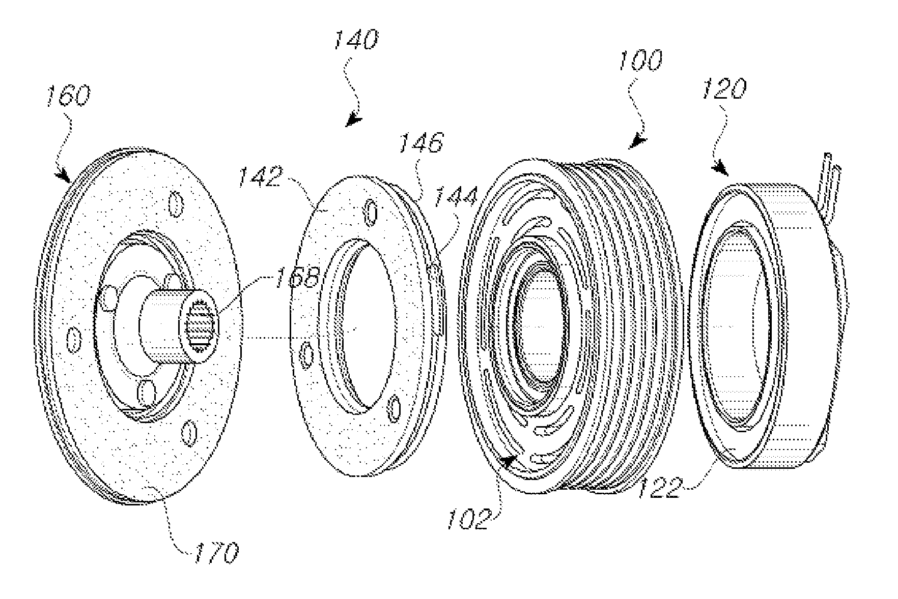
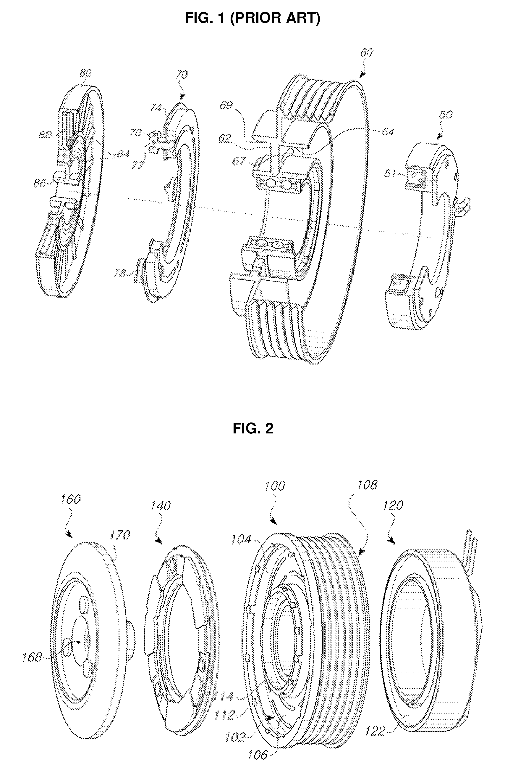
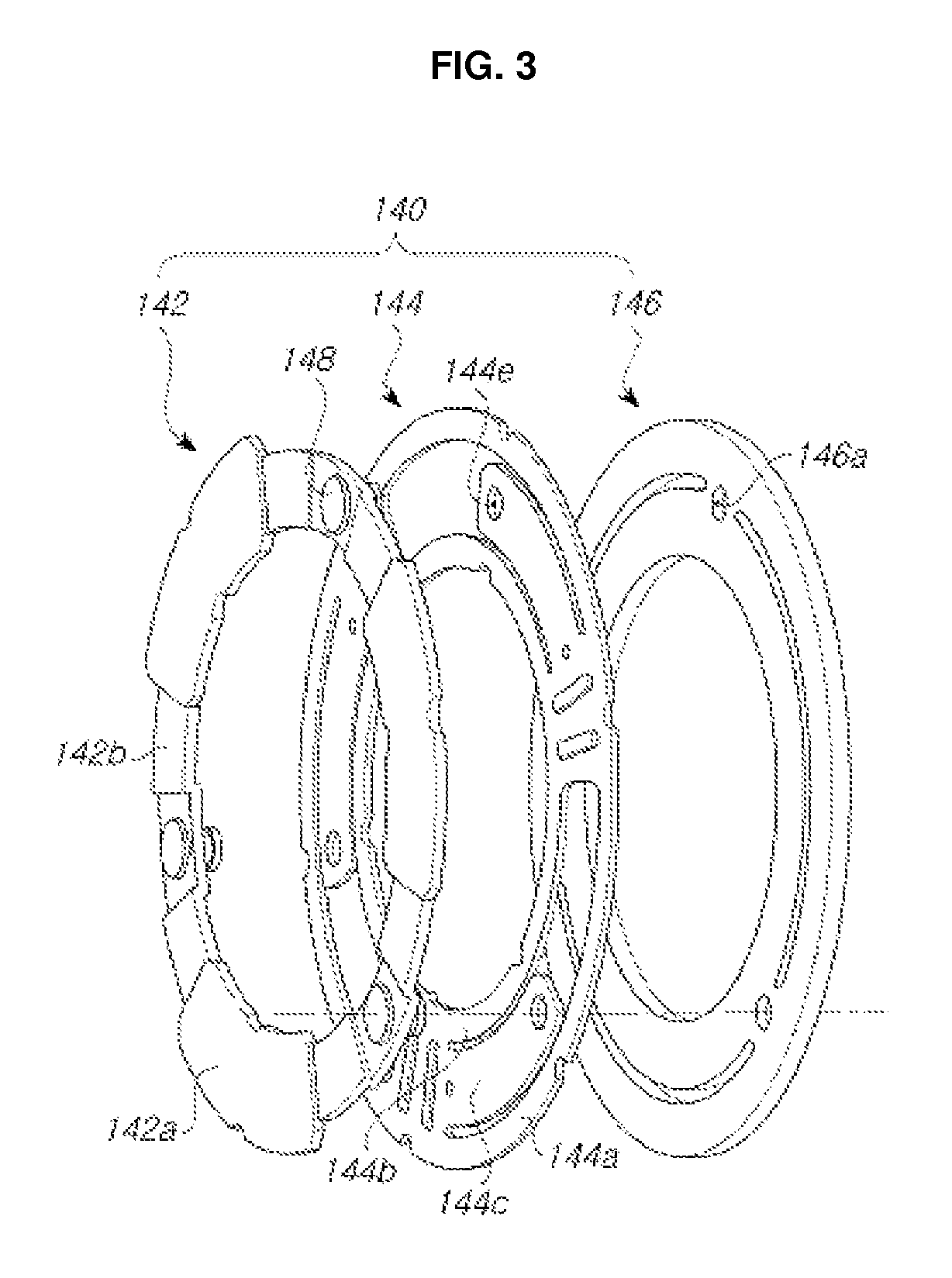
[0044]The friction ring 142 also has a roughly ring-like shape. In the present invention, the friction ring 142, which has frictional contact with the frictional contact surface 170 of the hub assembly 160, has a plurality of convex portions 142a relatively more protruded than the frictional surface thereof and a plurality of concave portions 142b relatively more depressed therethan, in an alternating manner. In this embodiment, three convex portions 142a and three concave portions 142b are formed.

[0045]The convex portions 142a and the concave portions 142b are coupled respectively to the convex portions and concave portions having the corresponding shapes thereto formed on the frictional contact surface 170 of the hub assembly 160, so that the rotary power is transmitted from the pulley 100 to the hub assembly 160. That is, as shown in FIG. 7, a plurality of concave portions 172 and a plurality of convex portions 174 are formed on the frictional contact surface 170 of the hub assem...

second embodiment

[0068]Referring next to FIGS. 8 to 10, an explanation on a power transmission device for a water pump according to the present invention will be in detail given.

[0069]According to the second embodiment of the present invention, as shown in FIGS. 8 and 9, a magnetic flux generating means 220 and a pulley 200 have the same configuration as those in the first embodiment of the present invention, except that the disk assembly and the hub assembly are different in configuration from those in the first embodiment of the present invention. Therefore, a detailed description on the same components as those in the first embodiment of the present invention will be avoided.

[0070]According to the second embodiment of the present invention, as shown in FIG. 8, in the same manner as the first embodiment of the present invention, a disk assembly 240 basically includes a disk 246, a resilient ring 244 disposed at the front surface of the disk 246 and the friction ring 242 disposed in front of the re...


PUM


Abstract

The present invention relates to a power transmission device for a water pump, including a pulley, a magnetic flux generator, a disk assembly, and a hub assembly, wherein the disk assembly has a disk, a friction ring for providing a frictional contact with the hub assembly, and a resilient ring adapted to pressurize the friction ring toward the hub assembly, so that when the attracting magnetic flux of the magnetic flux generator is not applied, the friction ring makes a frictional contact with the hub assembly through the resilient pressurization of the resilient ring, whereas, when it is applied, the disk moves toward the pulley to allow the frictional contact between the friction ring and the hub assembly to be released.

Description

REFERENCE TO RELATED APPLICATIONS[0001]This is a continuation of pending International Patent Application PCT / KR2010 / 008900 filed on Dec. 13, 2010, which designates the United States and claims priority of Korean Patent Application No. 10-2009-0129985 filed on Dec. 23, 2009, Korean Patent Application No. 10-2009-0129986 filed on Dec. 23, 2009 and Korean Patent Application No. 10-2010-0089584 filed on September 13, 2010, the entire contents of which are incorporated herein by reference.FIELD OF THE INVENTION[0002]The present invention relates to a power transmission device for a water pump, and more particularly, to a power transmission device for a water pump for cooling an automobile engine, wherein power regulation between a disk and a hub in the water pump can be accurately performed, rotation synchronization between them can be stably achieved, and the damage of the parts can be prevented.BACKGROUND OF THE INVENTION[0003]A water pump for a vehicle is adapted to pressurize and tr...

Claims


Application Information

Patent Timeline
Patent Type & Authority Patents(United States)
IPC IPC(8): F01P5/12F16D27/10F16D27/112
CPCF04B9/02F16D27/112F16H55/36F01P7/162
Inventor CHUNG, SUK-JAESEO, EUN-YOUNGOH, SUNG-TAEGGONG, SEONG-GYU
Owner HANON SYST
Why Eureka
Try Eureka