Tie down anchor

a technology of anchors and anchors, applied in the field of tie-down anchors, can solve the problems of difficult installation, large size, and heavy weight, and achieve the effect of superior holding ability

Inactive Publication Date: 2013-07-09
ZHOU WEI
View PDF13 Cites 6 Cited by
  • Summary
  • Abstract
  • Description
  • Claims
  • Application Information

AI Technical Summary

Problems solved by technology

Present solutions for having a great deal of holding power include auger type earth anchors that are difficult to install, quite large and usually heavy.

Method used


Image

  • Tie down anchor
  • Tie down anchor
  • Tie down anchor

Examples


Embodiment Construction

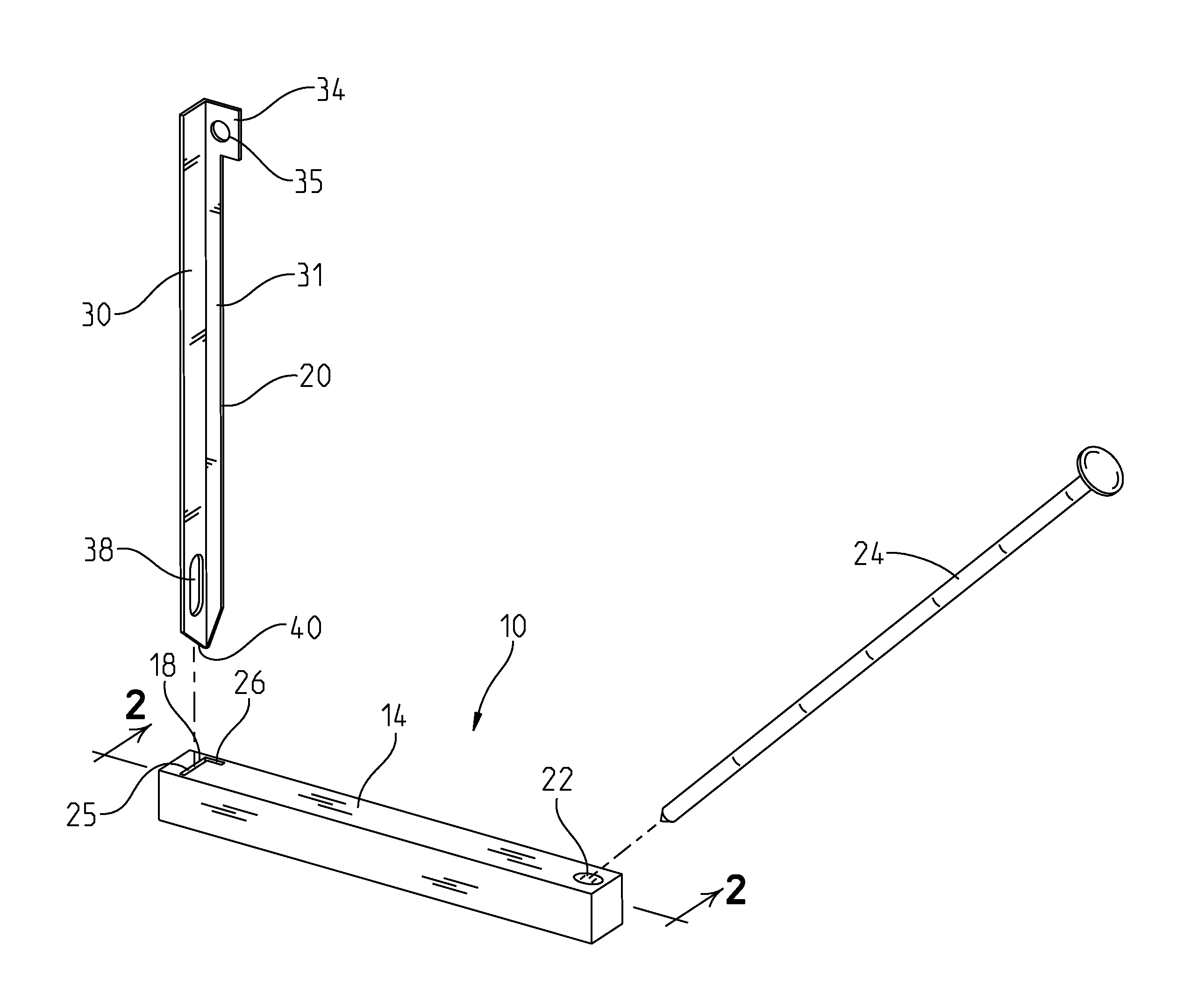
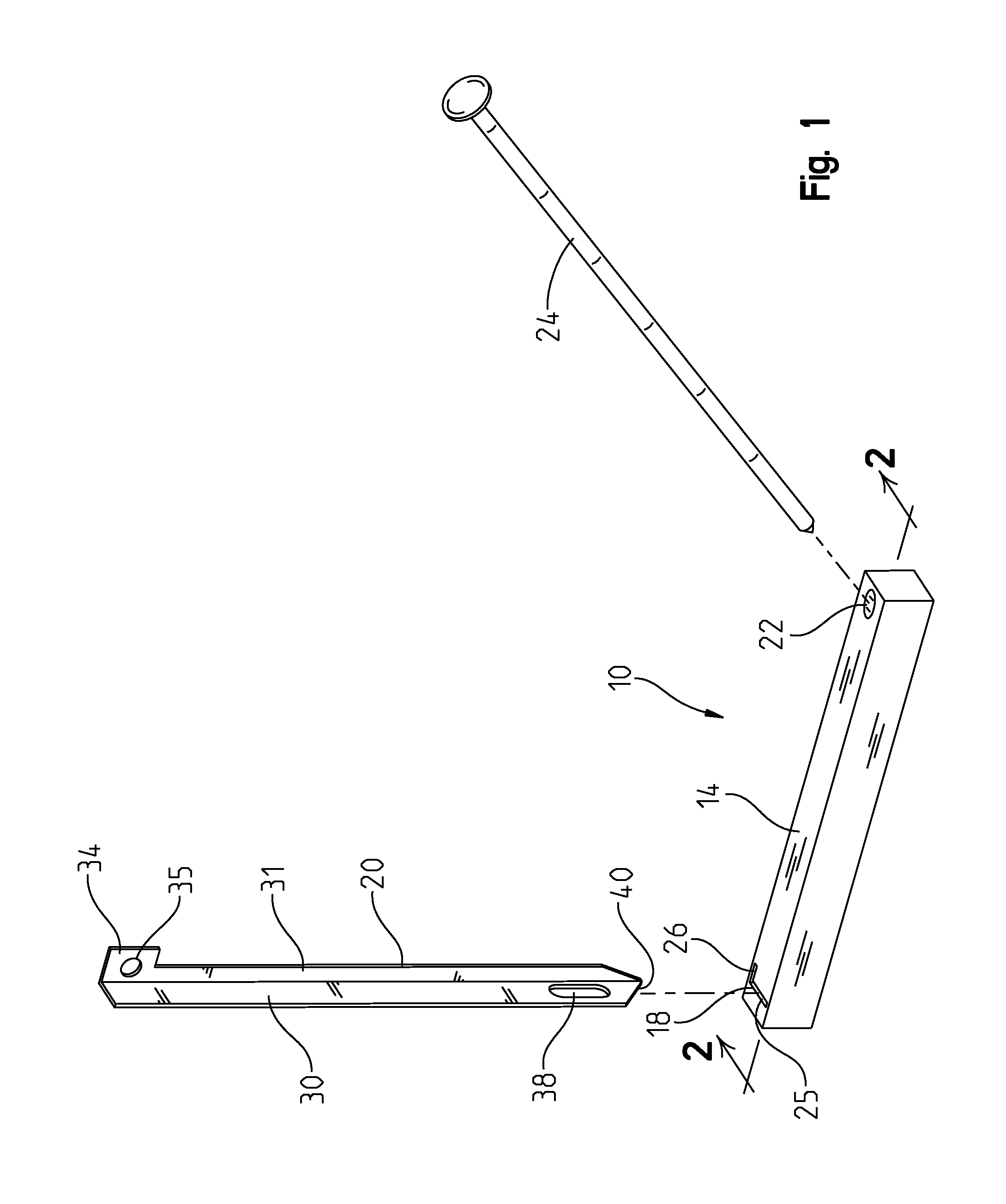
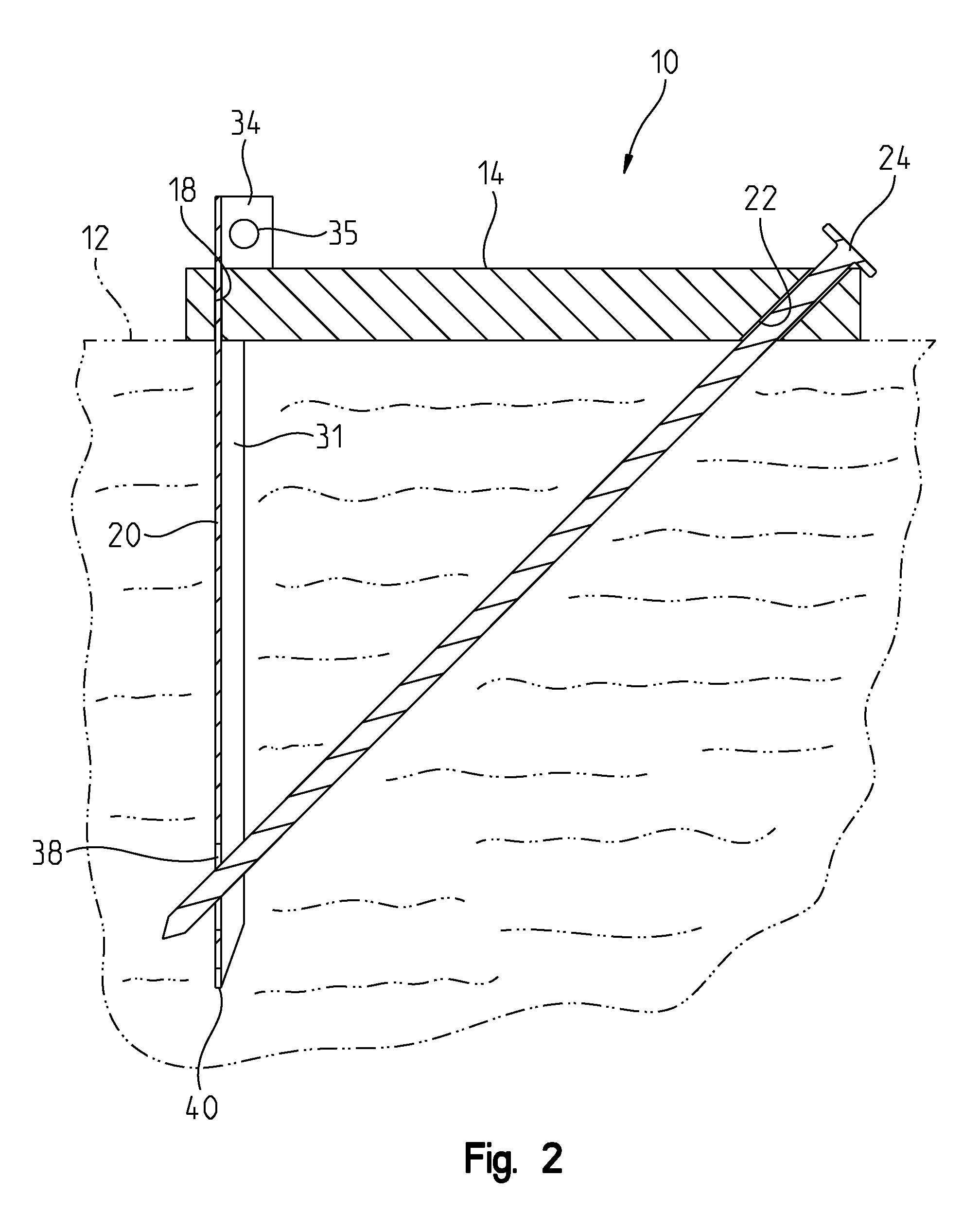
[0015]FIG. 1 shows the ground anchor 10 of the present invention in an exploded view. The ground anchor 10 is particularly useful for anchoring tents or other objects to the ground 12. FIG. 2 shows a sectional view of the anchor 10 as used in the ground 12. The anchor 10 has a guide 14. The guide 14 has a stake aperture 18 adapted for receiving a main stake 20 and an angled hole 22 adapted for receiving a locking stake 24. The angled hole 22 extends obliquely through the guide 14 and is angled toward the stake aperture 18 when traversing toward the ground 12 through the guide 14. The stake aperture 18 has legs 25 and 26 that are straight slots through the entire thickness of the guide 14. Leg 26 is shorter in length than leg 25. The guide 14 may be made of a solid block of material, as shown in FIGS. 1 and 2, or can be made of tubular stock. When the guide 14 is made of solid stock, as shown in FIGS. 1 and 2, it is easier to insert the locking stake 24 and the main stake 20 into the...


PUM


Abstract

A tie down anchor that is particularly useful when tying down objects to the ground and may take the place of ordinary tent stakes due to the tie down anchor's superior holding ability when compared to traditional tent stakes. The tie down anchor has a guide having an angled hole. A main stake extends downwardly from the guide and the main stake includes an aperture. A locking spike is adapted for being received in the angled hole. The aperture in the main stake is positioned to receive the locking stake when the locking stake passes through the angled hole. The stake of this invention is small, light, and of a comparable size to traditional tent stakes.

Description

BACKGROUND OF THE INVENTION[0001]Anchoring objects to the ground is important for temporary structures such as tents. Ideally an anchor would require a lot of force to remove from the ground while it is working, yet be easily removed when desired. The anchor should also be small when not in use so it may be easily stored. Present solutions for having a great deal of holding power include auger type earth anchors that are difficult to install, quite large and usually heavy. There is a need for an anchor similar in size to a traditional tent stake, yet provides holding power comparable to an auger type anchor.SUMMARY OF THE INVENTION[0002]The present invention is a tie down anchor that is particularly useful when tying down objects to the ground and may take the place of ordinary tent stakes due to the tie down anchor's superior holding ability when compared to traditional tent stakes. The tie down anchor has a guide having an angled hole. A main stake extends downwardly from the guid...

Claims


Application Information

Patent Timeline
Patent Type & Authority Patents(United States)
IPC IPC(8): E04H15/62
CPCE04H15/62
Inventor ZHOU, WEI
Owner ZHOU WEI
Why Eureka
Try Eureka