Oscillating positive expiratory pressure device

a positive and expiratory pressure technology, applied in the field of expiratory treatment devices, can solve the problems of affecting the bronchial obstruction, splitting open obstructed airways, and insufficient single cough to clear obstructions,

Active Publication Date: 2013-07-16
TRUDELL MEDICAL INT INC
View PDF144 Cites 61 Cited by
  • Summary
  • Abstract
  • Description
  • Claims
  • Application Information

AI Technical Summary

Benefits of technology

[0006]In one aspect, an OPEP device comprises a housing enclosing at least one chamber, a chamber inlet configured to receive exhaled air into the at least one chamber, and a chamber outlet configured to permit exhaled air to exit the at least one chamber. A channel positioned in an exhalation flow path between the chamber inlet and the chamber outlet is moveably connected to a chamber of the at least one chamber. Additionally, an air flow regulator is moveable with respect to the channel between a first position, where the flow of air through the channel is restricted and a second position, where the flow of air through the channel is less restricted. The air flow regulator is configured to repeatedly move between the first position and the second position in response to a flow of exhaled air. A weight of the air flow regulator offers a resistance to the flow of exhaled air through the channel during exhalation.

Problems solved by technology

However, for individuals suffering from more significant bronchial obstructions, such as collapsed airways, a single cough may be insufficient to clear the obstructions.
It is believed that OPEP therapy, or the oscillation of exhalation pressure at the mouth during exhalation, effectively transmits an oscillating back pressure to the lungs, thereby splitting open obstructed airways and loosening the secretions contributing to bronchial obstructions.

Method used


Image

  • Oscillating positive expiratory pressure device
  • Oscillating positive expiratory pressure device
  • Oscillating positive expiratory pressure device

Examples


first embodiment

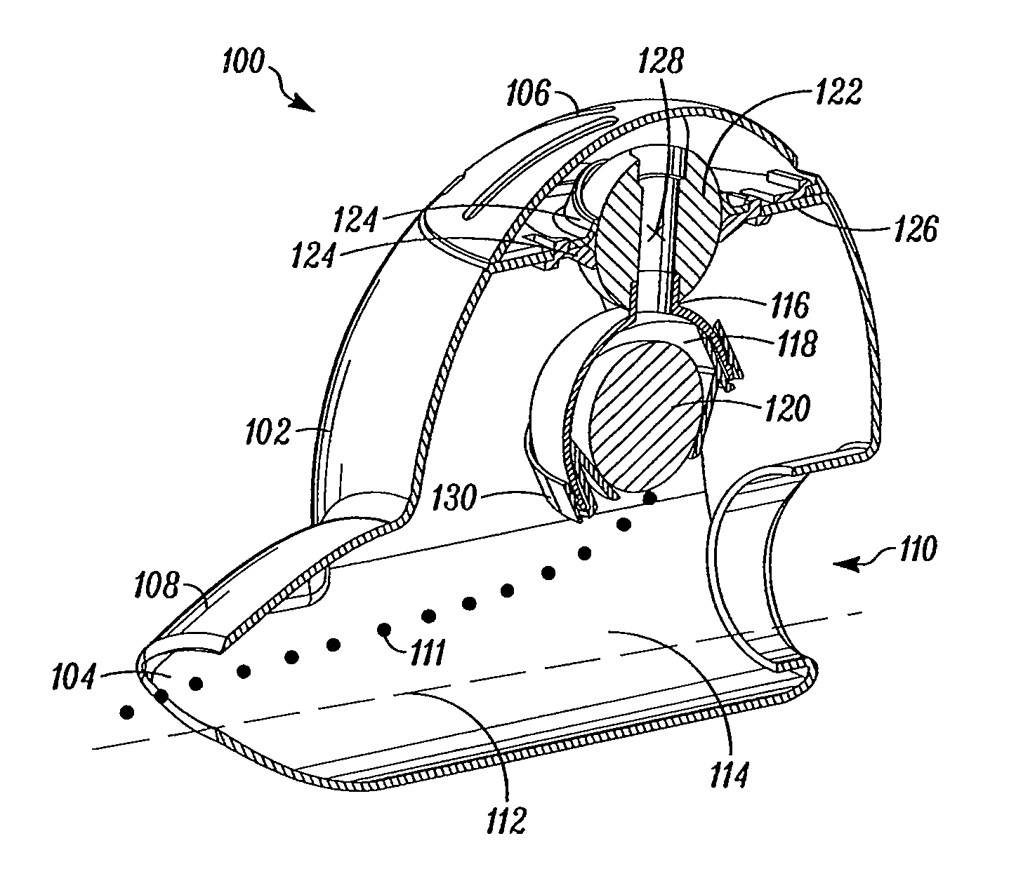
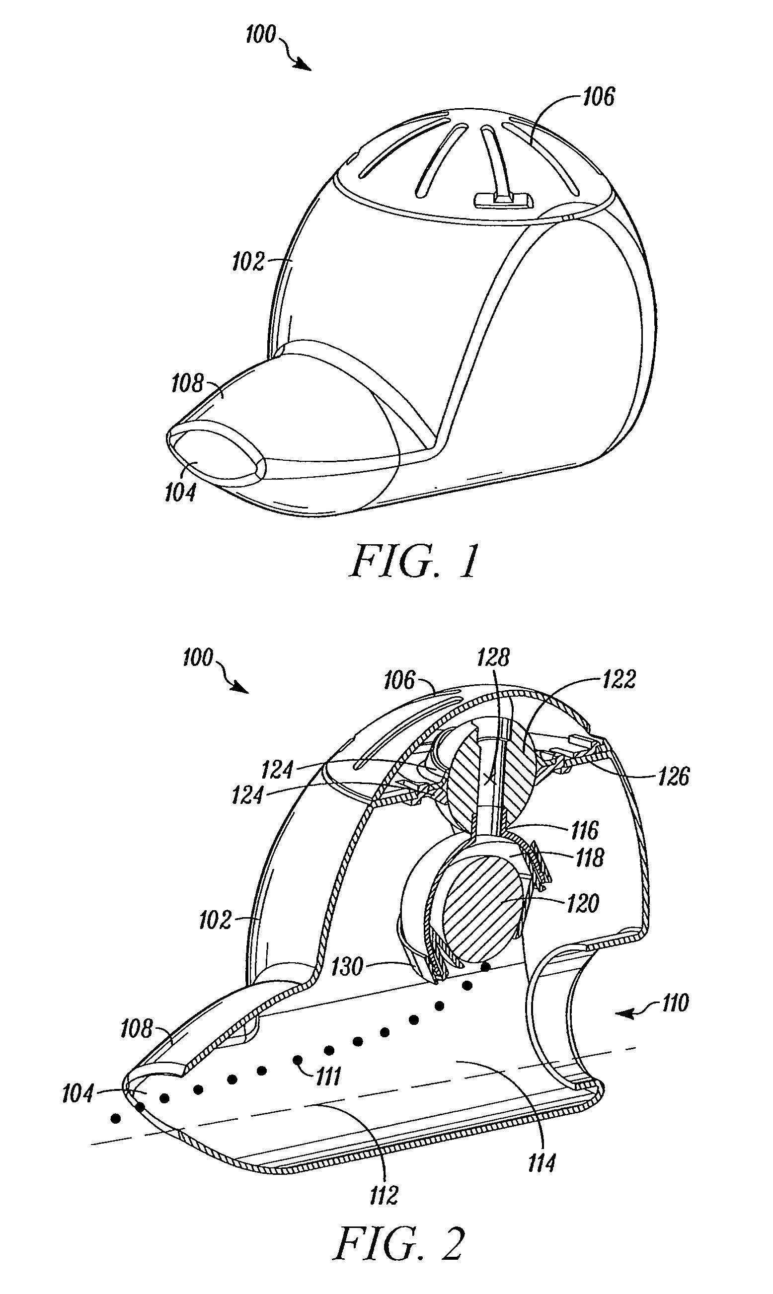
[0066]Referring to FIGS. 1-5, an OPEP device 100 is shown. In general, the OPEP device 100 comprises a housing 102 having an interior chamber 114, a chamber inlet 104, and a chamber outlet 106. The housing 102 may also be associated with a mouthpiece 108. Although the mouthpiece 108 is shown as being fixedly attached to the housing 102, it is envisioned that the mouthpiece 108 may be removable and replaceable with a mouthpiece 108 of a different size or shape. Alternatively, other user interfaces, such as breathing tubes or gas masks (not shown) may be associated with the housing 102. Preferably, the housing 102 is openable so that the chamber 114 and the parts contained therein can be periodically accessed, cleaned, replaced, or reconfigured. The housing 102 may be constructed of any durable material, such as a polymer (e.g., Acrylonitrile butadiene styrene).

[0067]In FIGS. 1-2, the housing 102 and the chamber 114 are generally spherical in shape. However, a housing of any shape cou...

second embodiment

[0081]Turning to FIG. 8, a cross-sectional perspective view of an OPEP device 200 is shown. In general, the OPEP device 200 comprises the same components as the OPEP device 100. More specifically, the OPEP device 200 comprises a housing 202, a chamber inlet 204, a chamber outlet 206, a mouthpiece 208, a nebulizer port 210 having a one way valve (not shown), a chamber 214, and a channel assembly 216. As with the OPEP device 100, the channel assembly 216 in the OPEP device 200 is connected to the housing 202 by a ball and socket joint, comprising a pair of socket walls 224 and a rotation ball 222.

[0082]Referring to FIGS. 8-9, the OPEP device 200 differs from the OPEP device 100 in that a user does not have to open the housing 202 to adjust the magnitude and direction of the normal force from the channel 218 acting on the air flow regulator 220. Rather, the OPEP device 200 comprises a gear train 234 that is connected to a truncated cone 232 and that extends through the rotation ball 22...

third embodiment

[0083]Turning to FIGS. 10-21, an OPEP device 300 is shown. The OPEP device 300 comprises a housing 302, a chamber inlet 304, a chamber outlet 306, and a mouthpiece 308. Although the OPEP device 300 is not shown as having a nebulizer port for connection to a nebulizer, a nebulizer port could be included in the same manner as described above in relation to the OPEP device 100.

[0084]Referring to FIG. 11, a cross-sectional view of the OPEP device 300 is shown. The OPEP device 300 includes a channel assembly 316 comprising an air flow regulator 320, a cup 336, an inner sphere 338, and an outer ring 340. A channel 318 is defined within the cup 336 and the inner sphere 338. As shown, the channel assembly 316 is moveably connected to the housing 302 by a first gimbal 342 such that the channel assembly 316 is rotatable about an axis defined between the first gimbal 342. Likewise, referring to FIG. 12, the inner sphere 338 is connected to the outer ring 340 by a second gimbal 344, offset nine...


PUM


Abstract

An oscillating positive expiratory pressure device comprising a housing enclosing at least one chamber, a chamber inlet configured to receive exhaled air into the at least one chamber, and a chamber outlet configured to permit exhaled air to exit the at least one chamber. A channel is positioned in an exhalation flow path between the chamber inlet and the chamber outlet, with the channel being moveably connected to a chamber of the at least one chamber. An air flow regulator is moveable with respect to the channel between a first position, where the flow of air through the channel is restricted and a second position, where the flow of air through the channel is less restricted, the air flow regulator being configured to repeatedly move between the first position and the second position in response to a flow of exhaled air.

Description

RELATED APPLICATIONS[0001]This application claims the benefit of U.S. Provisional Application No. 61 / 154,661, filed on Feb. 23, 2009, and U.S. Provisional Application No. 61 / 181,200, filed on May 26, 2009, which are incorporated herein by reference.TECHNICAL FIELD[0002]The present disclosure relates to an expiratory treatment device, and in particular, to an oscillating positive expiratory pressure (“OPEP”) device.BACKGROUND[0003]Each day, humans may produce upwards of 30 milliliters of sputum, which is a type of bronchial secretion. Normally, an effective cough is sufficient to loosen secretions and clear them from the body's airways. However, for individuals suffering from more significant bronchial obstructions, such as collapsed airways, a single cough may be insufficient to clear the obstructions.[0004]OPEP therapy represents an effective bronchial hygiene technique for the removal of bronchial secretions in the human body and is an important aspect in the treatment and continu...

Claims


Application Information

Patent Timeline
Patent Type & Authority Patents(United States)
IPC IPC(8): A61M15/00
CPCA61M16/14A61M15/00A61M16/00A61M16/0006A61M16/0866A61M11/06A61M16/208A61M15/0098A61M11/02A61M16/0057A61M16/20
Inventor MEYER, ADAMGULKA, NOELSCHMIDT, JAMES
Owner TRUDELL MEDICAL INT INC
Why Eureka
Try Eureka