Synchronous electric motor drive system
a technology of synchronous motors and drive systems, applied in the direction of motor/generator/converter stoppers, pulse generators, electric devices, etc., can solve the problems of periodic ripples and inconvenient maintenance of synchronous motors
- Summary
- Abstract
- Description
- Claims
- Application Information
AI Technical Summary
Benefits of technology
Problems solved by technology
Method used
Image
Examples
first embodiment
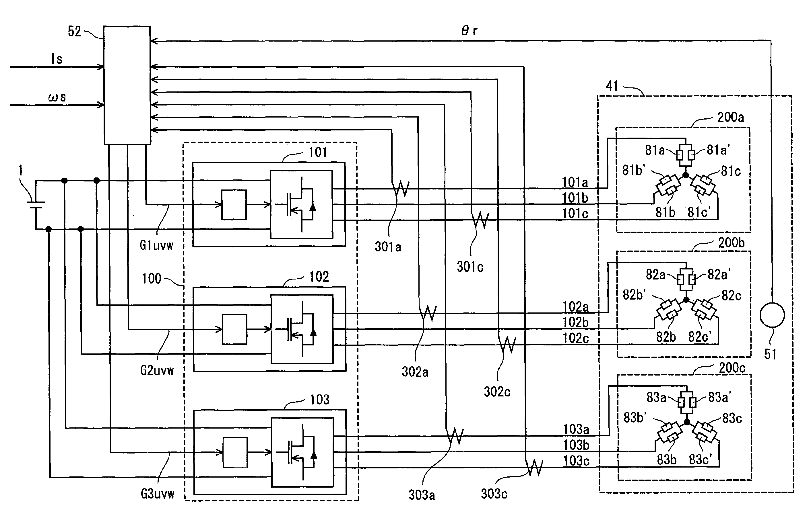
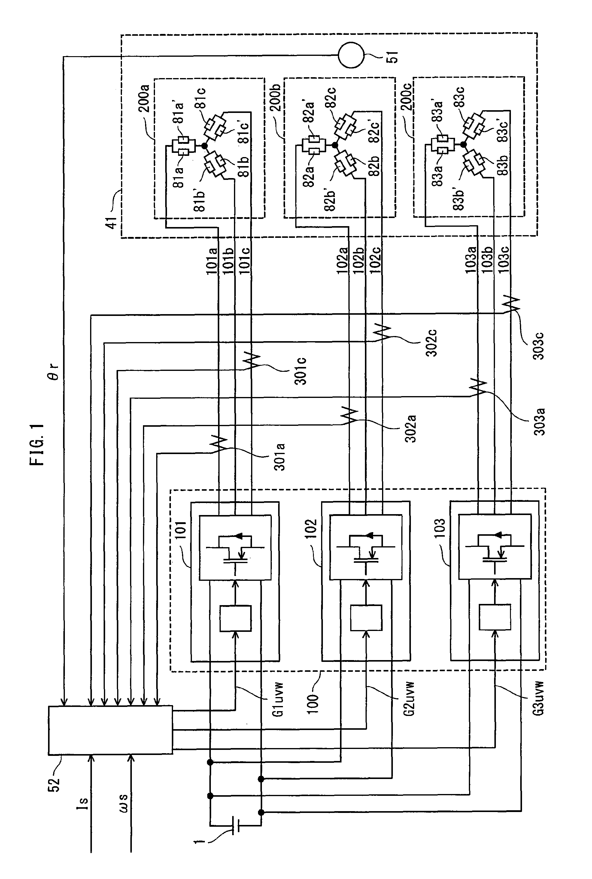
[0047]Firstly, a description is made of an overall structure of a synchronous motor drive system pertaining to the present invention. FIG. 1 shows the overall structure of the synchronous motor drive system of the present invention.
[0048]The synchronous motor drive system internally includes a DC power supply 1, an inverter module 100, a synchronous motor 41, and a current application control unit 52.
[0049]The inverter module 100 has inverters 101, 102, and 103, that perform DC / AC conversion according to gate control signals G1uvw, G2uvw, and G3uvw, respectively, to supply three-phase currents to the synchronous motor 41. Note that the inverter module 100 is characterized in that it accommodates all constituent switching devices of the inverters 101, 102, and 103 in one. The output currents 101a, 101b, and 101c from the inverter 101 are offset from each other by 2Π / 3 radians. Such an offset also applies to the output currents 102a, 102b, and 102c from the inverter 102 and the output...
modification 1
of the First Embodiment
[0111]A description is made below of a modification in which the present invention is applied to a synchronous motor drive system including two inverters. FIG. 14 shows an overall structure of the synchronous motor drive system pertaining to the present modification.
[0112]In the present modification, the synchronous motor drive system includes a DC power supply 1, an inverter module 104, a synchronous motor 44, and a current application control unit 53.
[0113]The inverter module 104 internally has inverters 105 and 106. The inverters 105 and 106 perform DC / AC conversion operations in accordance with gate control signals G1uvw and G2uvw to supply three-phase alternating currents to the synchronous motor 44.
[0114]The current application control unit 53 is a microcomputer system that controls the operations of the inverters 105 and 106 by outputting the gate control signals G1uvw and G2uvw. A ROM in the current application control unit 53 holds a plurality of map ...
modification 2
of the First Embodiment
[0141]FIG. 20 shows an overall structure of a synchronous motor drive system pertaining to a second modification. The synchronous motor drive system shown in the figure differs from FIG. 1 in the following two points. One is that the current application control unit 52 is replaced with the current application control unit 52a. The other is that the current detectors 302a, 302c, 303a, and 303c are removed.
[0142]The current application control unit 52 of the synchronous motor drive system shown in FIG. 1 performs feedback control of each of the inverters 101, 102, and 103, while checking the operation condition of each inverter by monitoring the current value and the current phase in a corresponding power wiring.
[0143]However, in synchronous motors including a plurality of three-phase coils, generally, current amounts and current phases are estimated with respect to all the three-phase coils according to the structure of the synchronous motor, simply by monitori...
PUM
 Abstract
Description
Claims
Application Information
 - R&D
- Intellectual Property
- Life Sciences
- Materials
- Tech Scout
- Unparalleled Data Quality
- Higher Quality Content
- 60% Fewer Hallucinations
Browse by: Latest US Patents, China's latest patents, Technical Efficacy Thesaurus, Application Domain, Technology Topic, Popular Technical Reports.
© 2025 PatSnap. All rights reserved.Legal|Privacy policy|Modern Slavery Act Transparency Statement|Sitemap|About US| Contact US: help@patsnap.com


