Synchronous electric motor drive system

a technology of synchronous motors and drive systems, applied in the direction of motor/generator/converter stoppers, pulse generators, electric devices, etc., can solve the problems of periodic ripples and inconvenient maintenance of synchronous motors

Active Publication Date: 2011-03-10
PANASONIC CORP
View PDF7 Cites 62 Cited by
  • Summary
  • Abstract
  • Description
  • Claims
  • Application Information

AI Technical Summary

Benefits of technology

[0012]With the structure described in Solution to Problem, the synchronous motor drive system pertaining to the present invention causes each three-phase inverter to supply current to a different coil group to rotate the synchronous motor. Accordingly, in the synchronous motor drive system of the present invention, induced field voltages produced by rotation of the synchronous motor may be divided in the three-phase inverters, thereby realizing high output power without boosting the voltage from the DC power supply by means of the boost circuit. Further, it is not necessary to apply a high voltage to the three-phase inverters and the motor. Due to this, there is no need to use switching devices having high breakdown voltage characteristics in the three-phase inverters. This prevents degradation of inverter efficiencies, such as an increase of on-state voltage caused by the use of the switching device having high breakdown voltage characteristics and an increase of switching losses caused by the high voltage switching operation. This also prevents an increase of iron losses in the synchronous motor caused by an application of high voltage. Moreover, in the synchronous motor mentioned above, coils are separately wound for each phase, and synchronous motor is driven by the same number of the three-phase inverters as the number of coils of the same phase. Consequently, the time constant as described above is small. In other words, even when the motor rotates at a high speed, a desired current waveform with a little distortion is obtained and torque ripple is fully reduced. Furthermore, each three-phase inverter may supply a three-phase alternating current having a different current phase angle and a different current amount. Accordingly, torque ripples generated in the plurality of coils are off set so that the generated torque ripples are cancelled by each other. As a result, a torque ripple generated in the motor drive as a whole is suppressed.
[0013]Accordingly, the synchronous motor drive system of the present invention reduces vibration and noise while maintaining high output power.
[0014]Furthermore, the current phase angle differences among the plurality of three-phase inverters are varied as determined by a current application control unit. Accordingly, the synchronous motor drive system allows the synchronous motor to drive at optimal current phase angle differences, without deliberately equalizing inductances between each coil at the time of the design of the motor or even without reducing the inequality in inductances due to a manufacturing error and such. Also, in the synchronous motor drive system pertaining to the present invention, optimal flux weakening control is executed in accordance with the changes in inductances that accompany the changes in drive state of the motor.

Problems solved by technology

However, torque generated by the synchronous motor is not kept constant and ripples periodically.

Method used


Image

  • Synchronous electric motor drive system
  • Synchronous electric motor drive system
  • Synchronous electric motor drive system

Examples


first embodiment

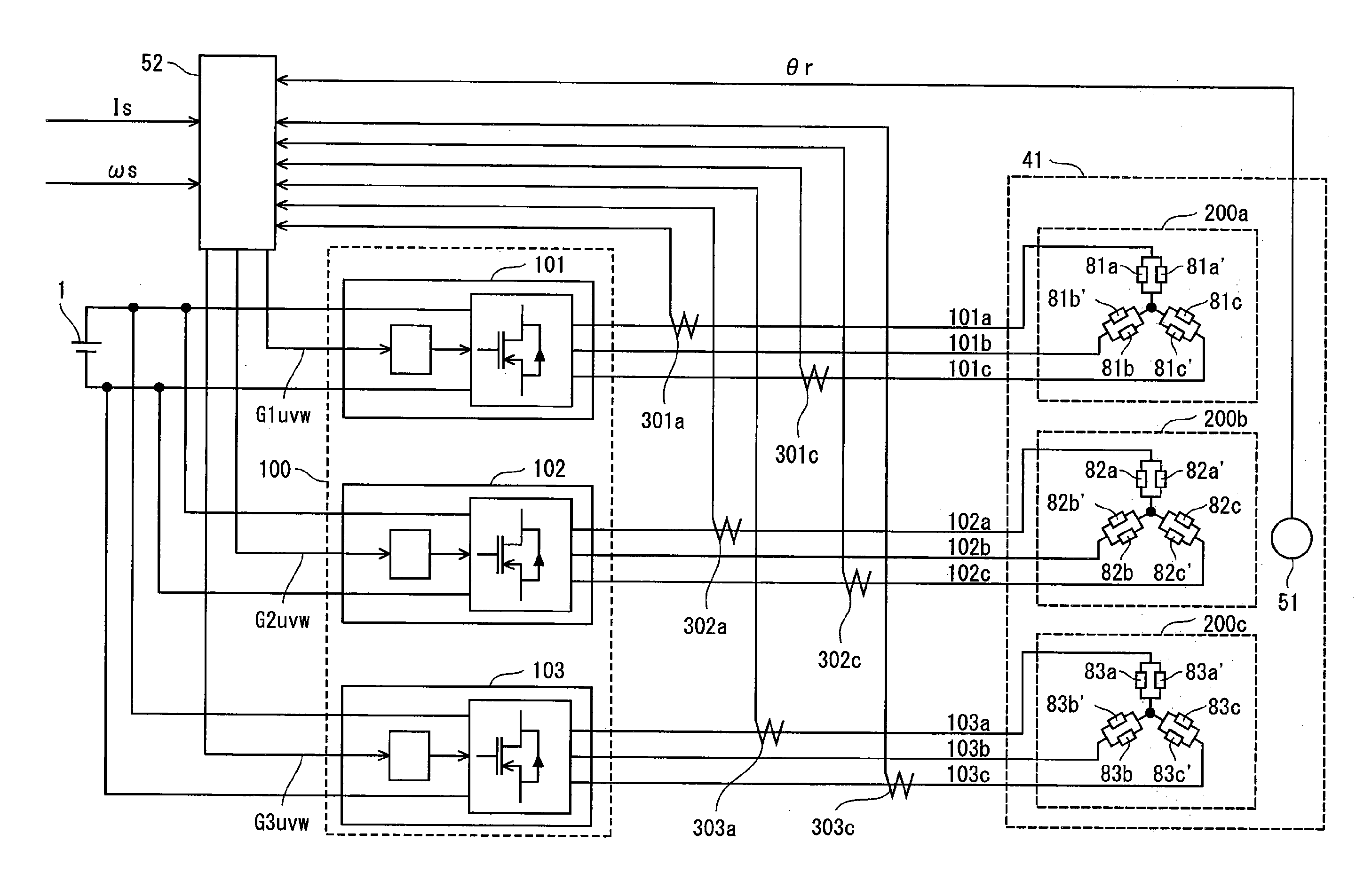
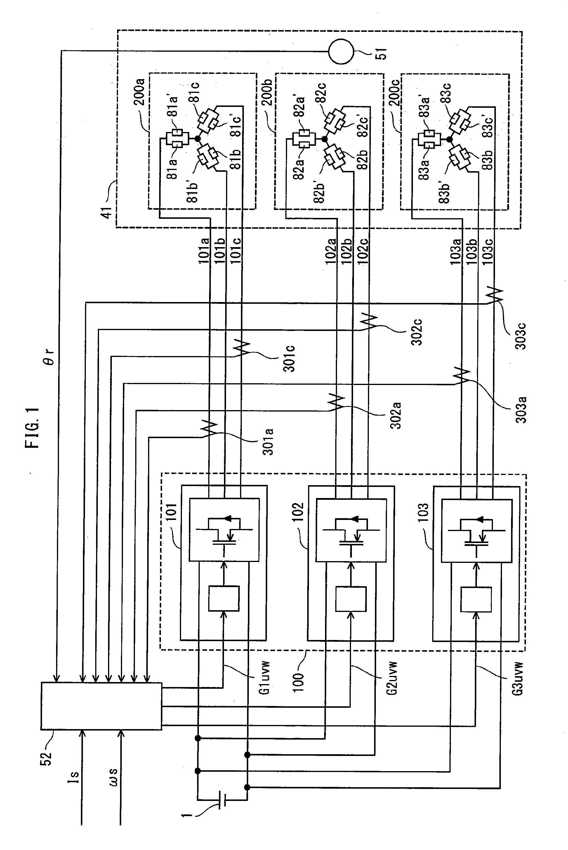
[0046]Firstly, a description is made of an overall structure of a synchronous motor drive system pertaining to the present invention. FIG. 1 shows the overall structure of the synchronous motor drive system of the present invention.

[0047]The synchronous motor drive system internally includes a DC power supply 1, an inverter module 100, a synchronous motor 41, and a current application control unit 52.

[0048]The inverter module 100 has inverters 101, 102, and 103, that perform DC / AC conversion according to gate control signals G1uvw, G2uvw, and G3uvw, respectively, to supply three-phase currents to the synchronous motor 41. Note that the inverter module 100 is characterized in that it accommodates all constituent switching devices of the inverters 101, 102, and 103 in one. The output currents 101a, 101b, and 101c from the inverter 101 are offset from each other by 2π / 3 radians. Such an offset also applies to the output currents 102a, 102b, and 102c from the inverter 102 and the output...

modification 1

of the First Embodiment

[0110]A description is made below of a modification in which the present invention is applied to a synchronous motor drive system including two inverters. FIG. 14 shows an overall structure of the synchronous motor drive system pertaining to the present modification.

[0111]In the present modification, the synchronous motor drive system includes a DC power supply 1, an inverter module 104, a synchronous motor 44, and a current application control unit 53.

[0112]The inverter module 104 internally has inverters 105 and 106. The inverters 105 and 106 perform DC / AC conversion operations in accordance with gate control signals G1uvw and G2uvw to supply three-phase alternating currents to the synchronous motor 44.

[0113]The current application control unit 53 is a microcomputer system that controls the operations of the inverters 105 and 106 by outputting the gate control signals G1uvw and G2uvw. A ROM in the current application control unit 53 holds a plurality Of map ...

modification 2

of the First Embodiment

[0140]FIG. 20 shows an overall structure of a synchronous motor drive system pertaining to a second modification. The synchronous motor drive system shown in the figure differs from FIG. 1 in the following two points. One is that the current application control unit 52 is replaced with the current application control unit 52a. The other is that the current detectors 302a, 302c, 303a, and 303c are removed.

[0141]The current application control unit 52 of the synchronous motor drive system shown in FIG. 1 performs feedback control of each of the inverters 101, 102, and 103, while checking the operation condition of each inverter by monitoring the current value and the current phase in a corresponding power wiring.

[0142]However, in synchronous motors including a plurality of three-phase coils, generally, current amounts and current phases are estimated with respect to all the three-phase coils according to the structure of the synchronous motor, simply by monitori...


PUM


Abstract

The present invention provides a synchronous motor drive system designed to realize reduced vibration and noise along with high output. The system includes: inverters 101, 102, and 103 for converting a direct current to a three-phase alternating current; a current application control unit 52 that controls operations of the three-phase inverters; and a synchronous motor 41 driven by three-phase alternating currents supplied from the three-phase inverters. The current application control unit 52 determines, for each three-phase inverter, a current phase angle and a current amount of a three-phase alternating current to output, and each inverter supplies a three-phase alternating current having the determined current phase angle and current amount to a different one of three-phase coil groups 200a to 200c.

Description

TECHNICAL FIELD[0001]The present invention relates to a synchronous motor drive system, and in particular to a technique for controlling inverters that supply drive current to a synchronous motor.BACKGROUND ART[0002]A synchronous motor is supplied with a three-phase alternating current from an inverter and rotates the rotor by causing the stator to generate magnetic fields by letting the current flow to coils mounted on the stator. A driving system of the synchronous motor flexibly controls the driving of the rotor by controlling the current applied to the coils appropriately in accordance with positions of magnetic poles of the rotor.[0003]However, torque generated by the synchronous motor is not kept constant and ripples periodically. This is due to the structure of magnetic circuits mainly determined by shapes of the stator and the rotor, as well as a current waveform of the current applied to the coils. The torque ripple is composed of ripple components each having a different p...

Claims


Application Information

Patent Timeline
Patent Type & Authority Applications(United States)
IPC IPC(8): H02P6/10B60L50/16
CPCB60L11/123B60L2220/14H02K3/28H02K21/12H02P6/142H02K29/08H02P2207/05Y02T10/6217Y02T10/641Y02T10/643Y02T10/7077H02P21/0089B60L15/007B60L15/20B60L2240/421B60L2240/423B60L2270/145H02P6/15B60L50/61B60L50/51Y02T10/64Y02T10/62Y02T10/72Y02T10/70H02P25/22Y02T10/7072
Inventor TAGOME, MASAKINISHIYAMA, NORIYOSHIKONDO, YASUHIROKITABATAKE, MAKOTOKAZAMA, SHUN
Owner PANASONIC CORP
Why Eureka
Try Eureka